Thanks owen. Those OEP transformers look pretty decent and are on the lower end of the price spectrum. Do they happen to have a US distributor? It doesn't really say so even though arrow and the other places are technically worldwide distributors.
Hi,
this instrumentation amplifier has many attractions.
Could the front end be strapped onto a different power amp?
What DC stability would result?
Would a DC servo be required?
Could the integrity of the balanced function be preserved if a DC blocking cap were inserted into the NFB loop to reduce DC gain to 1?
Any better way to extrapolate the inherent advantages of BWRX's creation to a mainstream amplifier?
dc is of no concern, the LM chips have a low offset voltage.
Just make shure that there is no "external" dc at the input, which could be amplified.
Regards
Just make shure that there is no "external" dc at the input, which could be amplified.
Regards
the LM chips have a low offset voltage.
With certain provisos. The layout must be good to minimise the possibility of oscillation, RF pickup, and other nasties.
Good tight layout, should provide good sound with average parts (and exceptional with great parts), and minimise the DC offset.
If you use a differential input pair of LM3975s as a balanced gainclone, you can trim the DC offset to produce a net zero easily, just beware that you may up the johnson noise as a result, if you have to use a higher resistance...
Have fun
Owen
It certainly could, but would most likely require modifications to the amp. DC stability would probably be good, thus a servo wouldn't be required.AndrewT said:Could the front end be strapped onto a different power amp?
What DC stability would result?
Would a DC servo be required?
I don't think this can be done. DC output offset is low and the source has the potential to be the main contributor. Any DC offset is amplified by the gain of the amp. 1mV at the input wlll be 20mV at the output with a gain of 20. Blocking DC at the input is the best option. Unfortunately that means using a coupling cap in the signal path.AndrewT said:Could the integrity of the balanced function be preserved if a DC blocking cap were inserted into the NFB loop to reduce DC gain to 1?
The simple solution would be to just put an IC instrumentation amp in front of an amp's input stage. I took this one step further with my design and combined the power output stage with the differential amp portion. As was mentioned recently, an input transformer will passively provide a similar solution with the added advantage of galvanic isolation.AndrewT said:Any better way to extrapolate the inherent advantages of BWRX's creation to a mainstream amplifier?
The LM chips have low DC offset, but poor layout and grounding can easily ruin this. DC coupling definitely requires low to no DC on the source signal. On my design with the inputs shorted to each other, the DC offset on each output is -8mV and -13.3mV. This will vary depending on resistor tolerances, op amp selection, and power op amp selection. With my computer's audio output connected as the source the DC offset increases to 50mV and 100mV.juergenk said:dc is of no concern, the LM chips have a low offset voltage.
Just make shure that there is no "external" dc at the input, which could be amplified.
20 of these PCBs are now up for sale in the trading post if anyone is interested.
http://www.diyaudio.com/forums/showthread.php?s=&postid=1163655#post1163655
http://www.diyaudio.com/forums/showthread.php?s=&postid=1163655#post1163655
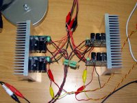
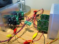
It took a while but the other boards got built, managed to find their way onto some heatsinks, and get wired up to a suitable power supply. I was going to fit 4 amps per heatsink but the 680uF caps I used were just barely too tall so 2 per sink was the decision. Quite overkill and as a consequence the aluminum chunks don't even get warm with my 8 ohm speakers. They could each be used separately for 4 channels but I've only got 2 speakers so why not bridge them? Since each board is an instrumentation amplifier bridging them is as simple as wiring the inputs in reverse polarity for each half of the bridge. The input impedance (inverting and noninverting) for each board is 100k, so using two in parallel gives 50k.
Currently the left channel uses OPA2134s for the input op amps and the right uses LM4562s. The OPA2134 channel has a small pop at turn on and plays a little music through the left speaker about 5 seconds after powering down the supply. The LM4562 channel has no pop at turn on and no noise when the supply powers down. So far the LM4562 sounds more precise than the OPA2134. The OPA2134 seems to have a slightly looser bottom end and slightly more shimmery top end, for lack of a better way to describe it.
Currently the left channel uses OPA2134s for the input op amps and the right uses LM4562s. The OPA2134 channel has a small pop at turn on and plays a little music through the left speaker about 5 seconds after powering down the supply. The LM4562 channel has no pop at turn on and no noise when the supply powers down. So far the LM4562 sounds more precise than the OPA2134. The OPA2134 seems to have a slightly looser bottom end and slightly more shimmery top end, for lack of a better way to describe it.
Attachments
Upon request, here is the schematic with all part values. These are what I am using on my boards with very good results.
C14, C15, C16, and C17 are optional EMI/RFI filtering caps. I would recommend at least using C16 or C14, C15, and C16 if possible. C14 and C15 should be 5% tolerance or better.
C9 is an optional rail to rail bypass cap. 100V rating minimum.
R13, R14 and R15, R16 may need to be recalculated if you plan on changing the zener voltages.
R17, R18 are optional loading resistors. Be careful of the rated power dissipation if you decide to lower their values. I would recommend using these to help ensure a symmetrical supply voltage and to help discharge the supply caps when the power is turned off. This configuration only has a small turn on click and a small turn off click accompanied by some other rather quiet noises due to the op amp supply rails discharging.
Q1, Q2 can be changed to any suitable NPN, PNP devices. 2N3904 and 2N3906 are cheap and widely available.
IC1 is the dual op amp. I'm using the OPA2134 but other devices may be used. I plan on trying the LM4562 when I get the itch to swap out the 2134.
IC2 is the chip amp. I'm using the LM3875 but other devices may be used as well. If you use a different chip you may change the feedback resistors to change the gain of the chip amp. Be careful with stability issues and lower gain settings.
The gain of this configuration can be changed with only one resistor - R11. 20k gives an overall gain of 20V/V. 10k gives an overall gain of 30V/V. Set your gain based on your source and power supply voltages. The gain formula is on the schematic.
BWRX what type of capos do you use for C13 to filter the zener? NP0?
Last edited:
- Status
- Not open for further replies.
- Home
- Amplifiers
- Chip Amps
- Instrumentation Gainclone