I can hardly tell about better sound. At this time I changed the whole enviroment.
But it sounded ok. 🙂
Btw why did you dropped the output inductor/resistor combination?
It may be useful with long cabling.
Regards
Juergen
But it sounded ok. 🙂
Btw why did you dropped the output inductor/resistor combination?
It may be useful with long cabling.
Regards
Juergen
I left out the resistor and inductor because they would take up a lot of space on the board and can be added off the board if they are needed.
BWRX said:I guess no one is interested in a board then? I'll be placing the order this week so you've got a day or so to let me know.
I've been following this thread with interest. Good work!
Is the price $20 for a stereo pair or per mono channel? You say "per board" below so I assume it's the latter. Anyway, I'd like to have 3 or 4 or 5 mono channels depending on price.
The odd one would be for my mono speaker testing amp. I just happen to be making it up right now. Let me know.
Jeff
jeff mai said:I've been following this thread with interest. Good work!
Thanks 🙂
jeff mai said:Is the price $20 for a stereo pair or per mono channel?
The price is per board and each board will give you a mono LM3875 amp. The pricing is just preliminary and may be a little lower if I can get the board house to give me a better deal. If you'd be interested in 5 boards then I would order a total of 20 and the price would be $18 per board. These will be very good quality boards which is why I don't mind paying a little more for them.
When I get home I'll post a picture of the layout to give a general idea of how the components are arranged.
I am still very interested in your project.
But as THEY say, timing is everything, and this is NOT a good time for me.
I wish for you great success.
-D
But as THEY say, timing is everything, and this is NOT a good time for me.
I wish for you great success.
-D
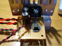
Here's a bare bones implementation of the instrumentation configuration. Lovingly cobbled together on high quality Radio Shack perfboard using only the finest bits and pieces lying around my workbench 😉
It's wired it up for 2 dual supplies so I can independently adjust the rail voltages for the opamp and LM3875.
It's wired it up for 2 dual supplies so I can independently adjust the rail voltages for the opamp and LM3875.
Attachments
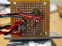
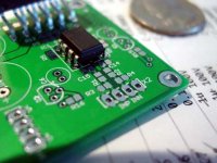
And the underside. Layout and wiring is straightforward since there aren't many parts. Removing the unused pins on the LM3875 helped make some space too. I opted not to include any bypass caps on either the opamp or LM3875 simply because I'm lazy and wanted to see how it works/sounds.
The blue body resistors on the top are 10k and 20k 1% metal film types. The two resistors on the bottom are 2k 5% carbon film types but I matched them to 1%. Matched resistor values are critical for proper operation of the instrumentation amp configuration.
The blue body resistors on the top are 10k and 20k 1% metal film types. The two resistors on the bottom are 2k 5% carbon film types but I matched them to 1%. Matched resistor values are critical for proper operation of the instrumentation amp configuration.
Attachments
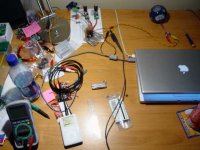
The prototype is up and running. I only have one amp so I hooked up my 8ohm speakers in parallel to at least get a front and center soundstage and used an old ipod as a source. To be honest I didn't expect it to sound this good at all! With no local decoupling and wires all over the place I expected at least audible hum from my speakers (90dB @ 1W/1m)... but there is none. Only if I put my ear right next to my speakers can I hear a faint white noise. DC output offset with the input shorted was about 10mV  The OPA2134 opamp supply is a regulated +/-12V (~100mA current capability) and the LM3875 supply is also a regulated +/-12V (dual LT1085 regulators with 23-24V unregulated but very stable input) with a lot more current capability.
As you can see below my setup isn't even close to being optimal
The OPA2134 opamp supply is a regulated +/-12V (~100mA current capability) and the LM3875 supply is also a regulated +/-12V (dual LT1085 regulators with 23-24V unregulated but very stable input) with a lot more current capability.As you can see below my setup isn't even close to being optimal
Attachments
I've put in an order for some PCBs, so in a few weeks I'll let you know how they work. If all goes well, I'll have about 20 extra PCBs and will put them up for sale in the trading post. At the quantity I ordered, pricing will be $15 per board. The boards will be 2 layer, 2oz. copper, green solder mask, double sided silk screen, with outer dimensions of 2" x 1.75" (nice and compact), mounting holes for 4-40 screws, and mounting hole center spacing of 1.75" x 1.5".

The sheer simplicity, ease of implementation, low cost, and moderate level of power that these chip amps offer was enough to pull me away from the class d stuff for a little bit 
Hi,
a nice layout, well done.
If I wanted to fit wired ended resistors, can the smd pads be drilled to insert the resistors in stand up mode? or are there traces on the other side? are the pads big enough for 0.7mm holes?
Matching of resistors for balanced mode cancellations should be better than 0.1%.
Why did you choose carbon for those two resistors?
Thanks Andrew.
There are traces and parts on both sides of the board and the pads are only 1.3mm x 1.5mm so you can't really drill through the surface mount pads. You could solder through hole resistors to the pads without drilling through them but it really is easier just to use surface mount resistors. I would have made a through hole part version but I'm used to working with SMDs and there's no way I could have made it as compact as the surface mount layout.
The feedback resistors should be matched as closely as possible, as should the input resistors and capacitors (if used). I plan to order 1% resistors and 5% or 2% C0G/NP0 caps and hand match them.
Those two carbon resistors on the bottom of the board are carbon simply because I didn't have 2kohm metal films.
BWRX said:I've put in an order for some PCBs, so in a few weeks I'll let you know how they work.
They were delivered earlier than expected and they gave me a couple extra boards for free. They usually do that when they want to fill a whole panel 🙂 Fit and finish are top notch as expected. Time to order parts...
Attachments

Hi Bwrx,
If I were to order/buy a pair of your PCBs, can you supply the SMD components with them?
I don't want to have to buy 100s for just a few.
If I were to order/buy a pair of your PCBs, can you supply the SMD components with them?
I don't want to have to buy 100s for just a few.
If you're interested in parts as well, I could probably do that. However, the parts I plan on getting will be good quality and may end up costing more than you'd be willing to pay. For example, the resistors I have in mind (for the feedback, filtering, and gain setting positions) are 0.1% metal film types that are about $0.70 each at a quantity of 10 or more. The important ceramic caps will be C0G 1 or 5% types (others are X7R 10%) which are also around $0.80 each for 10 or more. Looking at my current BOM the cost of parts will be in the neighborhood of $30 (at quantities for about 10-30 amps), including the LM3875TF chip. If you were to get all the parts from my BOM for two boards by yourself the cost would end up being about $40 for parts alone.
edit: sorry for all the edits, I was looking at the wrong parts on the BOM.
edit: sorry for all the edits, I was looking at the wrong parts on the BOM.
Hi,
you can cut your resistor costs by a factor of ten by matching 1% metal film to better than 0.1% without expensive equipment.
Not sure how you do that with SMD caps though.
Which are the ceramic caps that need accuracy?
I would be thinking NP0=C0G for bypass and maybe RF filtering. These would not need supreme matching.
AndrewT said:you can cut your resistor costs by a factor of ten by matching 1% metal film to better than 0.1% without expensive equipment.
That's what I had planned to do initially, but quickly realized that my meter isn't capable of matching to within 1% let alone 0.1%. The 0.1% metal film resistors from Panasonic are reasonably priced (less than a dollar isn't too bad) so I just decided I'd try those out. Using them will only hurt the wallet a little bit 😉
AndrewT said:Not sure how you do that with SMD caps though.
You could either do it with a very expensive capacitance meter or build your own measuring circuit based on something like a 555 timer. The main problem is how to properly connect the tiny caps in the circuit without actually soldering them.
AndrewT said:Which are the ceramic caps that need accuracy?
I would be thinking NP0=C0G for bypass and maybe RF filtering. These would not need supreme matching.
The input common mode RF filter caps need to be matched or they will throw off the CMR. Think of the input resistors and caps as a bridge circuit. If the bridge becomes unbalanced then CMR is reduced. Luckily there are only two of these caps. The other way to cut costs is to not use them at all, in which case I would populate resistors in their place. In most/some cases they may not even be needed. I would still use the differential filter caps across the input pins of the opamps and the input pins of the 3875 to ensure that RF signals are common mode.
- Status
- Not open for further replies.
- Home
- Amplifiers
- Chip Amps
- Instrumentation Gainclone