Hi all. I don't normally visit this forum since the class d forum is just so much fun 🙂 but I came over here because I'm thinking about building a gainclone to compare my own little creations to. Anyway, I was reading through the mauro penasa LM3886 thread (holy jeez it's a long thread) and checking out all the great info in there when mauro's ref schematic jumped out at me. It looked like an intrumentation amplifier configuration but it isn't. My next thought was "would it be possible and has anybody tried a configuration like that?"
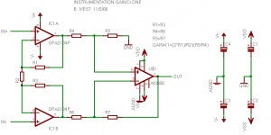
The instrumentation configuration would have some nice advantages like high common mode rejection, very high input impedance, a differential input, and a good low impedance buffer to drive the 3886 inputs. My question to the chip amp experts is whether or not a chip like the 3886 used as the differential amp in an instrumentation configuration would work or not? Check out the attached schematic to see what I'm talking about. R5 and R4 would have to be chosen so that the 3886 is stable, then you can fiddle with the gain of the buffers to get the overall gain you'd want.
The instrumentation configuration would have some nice advantages like high common mode rejection, very high input impedance, a differential input, and a good low impedance buffer to drive the 3886 inputs. My question to the chip amp experts is whether or not a chip like the 3886 used as the differential amp in an instrumentation configuration would work or not? Check out the attached schematic to see what I'm talking about. R5 and R4 would have to be chosen so that the 3886 is stable, then you can fiddle with the gain of the buffers to get the overall gain you'd want.
Attachments
I've been searching this whole time and finally found a thread (started earlier this year actually) with almost exactly the same schematic - right down to the use of the 2134 which just happens to be the package I use for dual opamps in a DIP8 package. But there's nothing saying if it was ever implemented. Anyone know if it was?
http://www.diyaudio.com/forums/showthread.php?postid=815986#post815986
http://www.diyaudio.com/forums/showthread.php?postid=815986#post815986
Nothing eh? Either the answer to my inquiry is very obvious and I've missed something in my searches or no one has tried this! Either way, I'll be placing a monster digikey order soon so I might as well add a few LM3886 chips to the heap so I can start experimenting.
Instrumentation amp
I used a 3875 as a stand alone differential amp, takes a little resistor fiddleling to get frequency and stability correct.
I think you should have good luck, I thought about useing a precision op amp in a feed forward error correction mode also.
Good Luck....
I used a 3875 as a stand alone differential amp, takes a little resistor fiddleling to get frequency and stability correct.
I think you should have good luck, I thought about useing a precision op amp in a feed forward error correction mode also.
Good Luck....
I think the reason the mauro penasa LM3886 circuit works well is because the op-amp is inside the feedback loop.
it looks like what you have is a balanced driver, but its right in front of the amp instead of in the preamp.
still it looks like it might be worth trying.
it looks like what you have is a balanced driver, but its right in front of the amp instead of in the preamp.
still it looks like it might be worth trying.
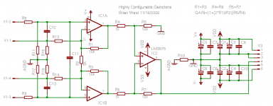
I've changed the previous schematic around so that not only the instrumentation configuration could be built, but also many other basic configurations as well. The resulting circuit is fairly simple and lends itself to easy routing with an LM3875 chip, which is the one I have selected to use for these boards. Introducing the highly configurable gainclone...
Would anyone be interested in a surface mount version of this board? The layout is all but finished and it uses 0805 and 1206 size parts and a DIP8 dual opamp package. Very simple, straightforward, and gives you many options as to what to build. If you don't want to do the intstrumentation configuration you can leave R2 open and use the opamp as a buffer. You can configure the opamp to be inverting with unity gain or higher or non-inverting and a gain of 2 or higher. Depending on which input you route the signal to you can have a non-inverting buffer/non-inverting 3875, inverting buffer/non-inverting 3875, or inverting buffer/inverting 3875. You can also choose to bypass the opamp completely and do an non-buffered inverting or non-inverting topology.
Lastly, is there anything anyone would like to see added? As I said, the layout is all but finished and the only thing I'm thinking of adding is an on board regulator for the opamp supply rails.
How necessary is the ~0.1ohm resistor in series with the output of the 3875? I was hoping that the series resistance of speaker cables alone would be enough... If not I'm sure it would be ok to connect a leaded resistor in series from the board output to a binding post (if necessary).
Attachments
It seems that you haven't read the datasheet and the application note AN-1192 carefully. I strongly advise you to do that.BWRX said:How necessary is the ~0.1ohm resistor in series with the output of the 3875? I was hoping that the series resistance of speaker cables alone would be enough... If not I'm sure it would be ok to connect a leaded resistor in series from the board output to a binding post (if necessary).
My opinion is that it is wise to have something between the amp and the speaker cable. Don't forget that 5-10 meters of cable is NOT a pure resistance! You have also 50-200 pF per meter also!
In my experience, the LM1875/3875 seem to be happy without the output resistor, but the LM3886/4780 and OPA 548/9 need it to run well.
peranders said:It seems that you haven't read the datasheet and the application note AN-1192 carefully. I strongly advise you to do that.
My opinion is that it is wise to have something between the amp and the speaker cable. Don't forget that 5-10 meters of cable is NOT a pure resistance! You have also 50-200 pF per meter also!
Hi Peranders. Thank you for your concern. I've read both very carefully and more than once now, honest! 🙂
So they're really that sensitive to what kind of cables are used? If I were to use a single strand of cat5 cable for the conductors and have them spaced an inch or two apart over the length of the cable I could have higher resistance and lower capacitance per meter than what you would normally expect. Do you think a series output resistor would still be needed with cables like that?
If I did build this and the 3875 didn't like whatever amount of capacitance there is on the output I could just as easily put a 5W resistor (and maybe an air coil connected parallel) directly between the output of the board and the binding post (assuming I'd ever get this is in a case!). I don't really see a problem with wiring it like that, do you?
pinkmouse said:In my experience, the LM1875/3875 seem to be happy without the output resistor, but the LM3886/4780 and OPA 548/9 need it to run well.
Hi Al. Do you remember what kind of speaker cable and load you have used with your 3875 based amps? Thanks for sharing your experiences with the different chips.
I now have built 2 LM3886 Guitar amps useing 2 seperate Guitar preamp designs, One Totally discreet useing Fets and NPN Transistors and one useing a OPA2134 (or any dual fet opamp)....
The LM3886 Power amp stage is the same with both amps and is basicly what is in the datasheet....
The discreet one sounds best to me for guitar but it doesn"t have much of a Clean sound , it has a pretty awesome distorted Crunchy sound which sounds great for Guitar and Bass....
If you want me to post the schematics for either preamp design let me know, They are both very simple and both use the same overdrive circuit which is a 4 stage cascadeing NPN Transistor over drive circuit....
Cheers
I've been thinking about the stability issues without the resistor in series with the output and the fact that I don't want to take any room on the board, so I was thinking that I could implement the low impedance resistor by just using a narrow trace instead. Any thoughts on this idea? I can't really see any drawback to doing this except for not being able to remove it 🙂
What do you guys think?
Attached is a shot of the layout so far. I also have another version that uses 3 terminal regulators instead of discrete regulators.
What do you guys think?
Attached is a shot of the layout so far. I also have another version that uses 3 terminal regulators instead of discrete regulators.
Attachments

Brian
Sorry I missed your earlier question about cables. I used various normal (79 strand) type cables, as well as 2.5mm2 pro speaker cable and cat5.
You could always just leave it off, and if required, you could just tack it on to the back of the binding posts.
Sorry I missed your earlier question about cables. I used various normal (79 strand) type cables, as well as 2.5mm2 pro speaker cable and cat5.
BWRX said:... so I was thinking that I could implement the low impedance resistor by just using a narrow trace instead.
You could always just leave it off, and if required, you could just tack it on to the back of the binding posts.
I'm interested in seeing how this project progresses. This is something I've been hankerin' to build myself, after reading AD's Inst Amp Guide. Makes sense to me.
BTW... Nice job on the PCB. I like it.
-David
BTW... Nice job on the PCB. I like it.
-David
head_spaz said:I'm interested in seeing how this project progresses.
For how simple this circuit is, it took me longer to finalize the design than I expected. They do say the
 is in the details...
Attached is the schematic. The design is flexible can be implemented with any chip amp provided you tweak the feedback resistor values to obtain stability and the gain you want. IC1A and IC1B are part of a dual DIP8 opamp package so that many different and readily available opamps can be auditioned. R1, C15, R2, C14, and C16 are optional (R1 and R2 would need to be jumpered if no filter is desired) and can be used for RF filtering. R3 and R4 are also optional and can be used to lower the input impedance.
R5, R6, R7, R8, R9, R10, and R11 are used in the instrumentation configuration. C17 is optional and can be used for further RF filtering, although it most likely won't be needed.
R12 is included for configuration flexibility. If you do away with the opamps you can configure the board to work as a simple inverting or non-inverting chip amp.
The opamp will of course need power, so a simple +/- discrete regulator (emitter follower with zener reference) is tightly integrated into the layout. It has the option of drawing power from the high voltage rails of the chip amp or from another separate external supply. Resistors between the emitters of the transistors and ground allow the opamp supply to be biased at a certain current if desired.
Attachments
The board I designed is 2" by 1.75" and uses the LM3875. It is a double sided board that uses all surface mount components (0805 size or larger) except for IC1 (DIP8 dual opamp), IC2 (LM3875), C1 (5mm lead spacing, 13mm diameter electrolytic), C2 (5mm lead spacing, 13mm diameter electrolytic), Q1 (TO92 NPN), and Q2 (TO92 PNP).
I chose the LM3875 because it has a good reputation, medium power capability, and a good pin out.
I have 6 LM3875 chips and will eventually be ordering at least 10 boards (2 layer, 2 oz copper, green solder mask, and silk screen on both sides). If anyone is interested in an excellent quality PCB for an LM3875 please let me know. The cost would be about $20 per board for 10 boards, $18 per board for 20 boards, and $15 per board for 50 boards.
BWRX said:It is a double sided board that uses all surface mount components (0805 size or larger) except for...
I forgot to include C5 and C6. They are also through hole electrolytic caps (2mm lead spacing and 5mm diameter).
I´ve been running LM3886/LM3876 for several years as differential amplifier.My next thought was "would it be possible and has anybody tried a configuration like that?"
Square wave response with reactive load was improved over the typical circuit. I don´t know why. This may be because both opamp-inputs see equal impedance or just because of different layout.
Last year I rewired the circuit back to noninverting operation because I wanted to use a preamp with varying output impedance (a simple potentiometer!).
In this configuration I can´t stand the hum because the simple differential amplifier needs matched source impedance for good common mode rejection.
An input buffer transforming the diff. amplifier to an instrumentation amplifier would have been another option.
But I had no time to do that.
Regards
Juergen
juergenk said:I´ve been running LM3886/LM3876 for several years as differential amplifier.
Square wave response with reactive load was improved over the typical circuit. I don´t know why. This may be because both opamp-inputs see equal impedance or just because of different layout.
Square wave response may have improved but did it sound any better to you? The difference amp gives you the option to use the one side of the output feedback resistor to sense your reference voltage. If your previous circuit had grounding issues (sound like it might have since you had audible hum) that could be part of the reason for the improved response.
I guess no one is interested in a board then? I'll be placing the order this week so you've got a day or so to let me know.
- Status
- Not open for further replies.
- Home
- Amplifiers
- Chip Amps
- Instrumentation Gainclone