I went to a 10 times smaller step and get more consistent THD values almost independent of frequency and number of cycles. Still overly optimistic, but if consistent, I can assume a factor and maybe be close enough. In other words, I know the circuit measures around .003, and It now simulates .00013. Changes would be relative and that is actually all that is needed.No help on my over optimistic THD measures or if I am interpreting my phase margin correctly?
Am I doing my stability margin correctly?
Run .ac. Closed loop. Look at the Bode plot on both sides of the input diff pair. See what the phase difference is when gain drops to zero.
Run .ac. Closed loop. Look at the Bode plot on both sides of the input diff pair. See what the phase difference is when gain drops to zero.
I am doing something wrong with the Titan probe. Never got it to work. Think I need to read it again.
Is my method valid? I used it for my current amp and it has remained stable. I no longer have a working scope to double check it.
Is my method valid? I used it for my current amp and it has remained stable. I no longer have a working scope to double check it.
It works for me but two things:
1. It uses two "step" runs so you have to include the .step .... directive.
2. Copy and paste the probe resulted in renaming Vi to Vi1 and Ii to Ii1, so you have to fix that, by renaming them back to Vi and Ii.
OK 3. rename the plt.txt file to just plt to save the plot. DIYA does not allow plt files. This needs to be a generic ".inc titan.plt" but that doesn't seem to work???
Attachments

Last edited:
Ok, this is almost as good.
1. Copy C:\Users\%userprofile%\Documents\LTspiceXVII\examples\Educationaland\LoopGain2.plt and renamed it just titan.plt. Put it in your design folder, etc.
2. Run the simulation that includes the probe.
3. Click on the blank trace dialog. This changes the menu items to include "Plot Settings".
4. Near the bottom is "Open plot Settings File".
5. Select "titan.plt" instead of the default.plt file.
Or, you could probably just "Open plot settings file" directly from C:\Users\%userprofile%\Documents\LTspiceXVII\examples\Educationaland\LoopGain2.plt
Last edited:
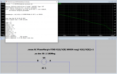
Progress? I managed to find a way to measure phase margin. You can do this to the Tian probe, but it gets messy, and the LTC Spice measure command/dialog has some parsing issues. It keeps forgetting the righthand side and fails when you change the sign... So here I will just use a simple feedback probe. The idea is to measure the loop gain at the point where it is 0dB; point being to get the phase.
PS: It's very impressive that the Tian probe works anywhere but I don't care. I just want a simple probe that works for audio amplifiers where the output is at least 1V. BTW, can someone explain what "u" in the "u{prb}" stimulus parameter is?
PS: It's very impressive that the Tian probe works anywhere but I don't care. I just want a simple probe that works for audio amplifiers where the output is at least 1V. BTW, can someone explain what "u" in the "u{prb}" stimulus parameter is?
Attachments
Last edited:
Here some things that came out of a current project, it shows some trouble and there solution(s) building a transformer based AC power supply.
(oops files are in the next post)
(oops files are in the next post)
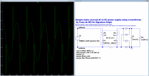

A very interesting issue. There are more mysteries I've not unraveled in your simulations, but the offset is the result of the initial conditions and a very long settling time. The simplest way to avoid the offset is to start the AC voltage at 90 (or 270) degrees where the inductor current is normally zero crossing. This begs the point, is it best to power a transformer/motor etc. this way and not at the classical voltage zero crossing.Here some things that came out of a current project, it shows some trouble and there solution(s) building a transformer based AC power supply.
(oops files are in the next post)
Attachments
The mystery in FdW's simulation is why does it ~hang if you simulate more than 0.5 seconds. This is important because if you simulate ~5 seconds or more, you can see the offset slowly settle away. I discovered it's about floating nodes, or nearly floating. FdW put a bleed resistor in an odd place and that would work except the diodes do not provide a good ground reference so both primary and secondary are sort of floating. By grounding "neutral", all is well, and it simulates in a flash, even at 5 seconds where the offset is almost gone. There are lots of other ways to fix this, but you need to be aware of the simulation process and always provide a well defined voltage wrt ground.
Attachments
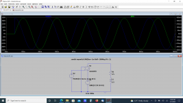
As the picture shows the circuit runs fine for 5 seconds and needs no second ground connection.
I would not advise that second ground connection and bring the 'full' effect of the mains ground into my circuit.
There is no floating path(s) in the circuits shown.
And having the need to run the simulation for 5 or even more seconds is not realistic in more complex circuits, using the soft-start is a simple effective solution.
There is no reason for the circuit to 'hang' after 500ms, the circuit is just an example to show how to stabilize the output voltage in 500ms or less.
Yes it is important to be able to simulate more than 5s at a time, but larger circuits will take 10's minutes run(simulation) time and waiting for large PSU (or even small) offsets to dissipate is not very useful. If your simulation speed is 1ms per minute (for larger circuits) will render waiting for 5s almost impossible.
Floating circuits will never succeed.
The bleed resistors are placed symmetrical (just an gimmick [aye candy])
The pictured simulation runs for 10s and shows 100ms of data
I would not advise that second ground connection and bring the 'full' effect of the mains ground into my circuit.
There is no floating path(s) in the circuits shown.
And having the need to run the simulation for 5 or even more seconds is not realistic in more complex circuits, using the soft-start is a simple effective solution.
There is no reason for the circuit to 'hang' after 500ms, the circuit is just an example to show how to stabilize the output voltage in 500ms or less.
Yes it is important to be able to simulate more than 5s at a time, but larger circuits will take 10's minutes run(simulation) time and waiting for large PSU (or even small) offsets to dissipate is not very useful. If your simulation speed is 1ms per minute (for larger circuits) will render waiting for 5s almost impossible.
Floating circuits will never succeed.
The bleed resistors are placed symmetrical (just an gimmick [aye candy])
There is no need for any reference at the diodes or there about, they are fine as they are.except the diodes do not provide a good ground reference
Sort off? no way.and secondary are sort of floating
There are people using (or at the least) testing/simulating for 'un-polarized' mains connections. Better not to trust the socket.By grounding "neutral", all is well
Almost may not be good enough and in some slower running simulations it may be impossible to simulate 5s of 'real' time.even at 5 seconds where the offset is almost gone
Fix what? there is nothing broken. And if so then show us how to stabilize that 'slow' psu in less then 500ms simulated real time.There are lots of other ways to fix this
The pictured simulation runs for 10s and shows 100ms of data
Yes I know, and that is what I was offering to solve with the 'soft-start' generated.but the offset is the result of the initial conditions and a very long settling time
Not (at the least always) true, try it ad 90deg to the sinus formula ad see the offset is still there.The simplest way to avoid the offset is to start the AC voltage at 90 (or 270) degrees
In real life you do not have that luxury, starting the circuit at 90deg may lead to large run-in currents, we all have seen the situation where a mostly well behaved circuits at one un-lucky moment blows the mains fuse.This begs the point, is it best to power a transformer/motor etc. this way and not at the classical voltage zero crossing
Attachments

Last edited:
These are no 'bleed' resistors, the resistors represent the isolation resistance between the mains and the application circuit (e.g. the leakage resistance of the transformer witch is (may be) extremely high). As noted before a floating circuit will not simulate and these where added to satisfy the need to un-float the otherwise floating mains (left) part of the circuit including the primary inductor.... FdW put a bleed resistor in an odd place and that ...
P.s. the value set is 1G and is the lowest (somewhat) acceptable value for mains isolation any value up to a few J-ohms(e.g. Jigo-ohms) will be acceptable. https://backtothefuture.fandom.com/wiki/Jigowatt
Last edited:
1. Most transformers have no soft start circuits, so the inrush current, ignoring secondary issues, can be 2x the running reactive current, but the reactive current should be small fraction (~"5% of the full load current on the primary") of the in-phase loaded current, so maybe it's not an issue?
2. I don't think it's legal nor likely that the mains is not grounded somewhere. L1 and L2 may be complimentary voltages with their center grounded, but they always have a ground reference at the source. If you really want to simulate a floating mains, then you have to model the mains wire capacitance etc, etc.
3. For the purposes of the simulator, all nodes need a well defined voltage wrt ground, even if that is via a huge value resistor. You can't simulate the undefined. My point is that there is no point waiting minutes for a simulation to run when all you have to do is make nodes well defined so that the simulation quickly converges. It's kind of abusing the tool. With the diodes the only path to ground, there is a point (zero crossing) in the AC cycle when all diodes are "open" and hence the transformer is ~floating. Another solution is to use real diodes instead of the default model because real diodes have leakage similar to a bleed resistor. I have tested this.
BTW, this power supply is about 21Watts. A 50VA 240VAC 50Hz transformer should have a primary inductance of about 70 Henries and a 25VA transformer about 140 Henries. The reactive current is very high in your simulation because you set the primary at 2.5H, which would imply a 1500VA transformer???
This was just intended as a 'playful' model, I should have noted that thanks.BTW, this power supply is about 21Watts. A 50VA 240VAC 50Hz transformer should have a primary inductance of about 70 Henries and a 25VA transformer about 140 Henries. The reactive current is very high in your simulation because you set the primary at 2.5H, which would imply a 1500VA transformer???
1: The model was just intended as a demonstrator of the solution (using a calculative soft start)1. Most transformers have no soft start circuits, so the inrush current, ignoring secondary issues, can be 2x the running reactive current, but the reactive current should be small fraction (~"5% of the full load current on the primary") of the in-phase loaded current, so maybe it's not an issue?
2. I don't think it's legal nor likely that the mains is not grounded somewhere. L1 and L2 may be complimentary voltages with their center grounded, but they always have a ground reference at the source. If you really want to simulate a floating mains, then you have to model the mains wire capacitance etc, etc.
3. For the purposes of the simulator, all nodes need a well defined voltage wrt ground, even if that is via a huge value resistor. You can't simulate the undefined. My point is that there is no point waiting minutes for a simulation to run when all you have to do is make nodes well defined so that the simulation quickly converges. It's kind of abusing the tool. With the diodes the only path to ground, there is a point (zero crossing) in the AC cycle when all diodes are "open" and hence the transformer is ~floating. Another solution is to use real diodes instead of the default model because real diodes have leakage similar to a bleed resistor. I have tested this.
2: I did not say that, but the output side of a doubly isolated psu may be isolated (galvanically) from mains
3: I do not agree, simulations should follow actuality as much as possible (and also read my previous answers)
Also the number of H's in the primary coil differs hugely with transformer quality and design metrology applied by the designer (yes the 2.5H is way off). The post was not intended as a source of good transformer design rules.
Last edited:
Hi All,
I wonder if anyone here has some experience with "converting" PSpice model files to LTSpice files? I have set up the attached circuitry (from Elektrotanya & originally courtesy 1audio) which is a DIY high speed oscilloscope probe. However, although LTSpice autogenerates the BF998 symbol with the PSpice model downloaded from onsemi (I think it was) - which supposedly is correct - when testing the circuitry I get these errors:
Attachment 1: The schematic ...
Image 1: I get this error 5 times - corresponding with the number of capacitors listed in the model (C13-C24)
Image 2: I also get this error after the five capacitor errors. Oddly, because there are other inductors with the same syntax ... ?
Image 3: And then finally this error list ...
My guess would be that it is some kind of syntax error between the BF998 model (PSpice) and LTSpice's model structure - I just can't work out what it may be ...
Would anyone happen to know about this? Maybe have a paper/link which describes what is needed to convert from PSpice to LTSpice model format?
Thanks for any help in this 😉
Jesper
Attachments
- Home
- Design & Build
- Software Tools
- Installing and using LTspice IV (now including LTXVII), From beginner to advanced