Thank you Ian, this is very helpful! Do I understand correctly that this LM3886 model created by Mooly is a proper SPICE model created from discrete components rather than the TI generic LM3886 model?
All the best,
Thanks Steve, I did actually find that model before and it worked for me fine (except for the floating nodes which I also encountered) the only reason I wanted to use the other TI PSpice model was that it was the most up to date. However, now seeing Moolys model makes the other ones useless?Ok, some ~minor issues with Mark's model. The error log lists some "ERROR:.... floating NODE.." . I'm not sure I understand this completely, but it looks like these "ERRORs" are from these GRUn lines that define a G that has only 2 nets and the current is defined as the voltage/1e6 or some other value. How this is not a resistor, I dunno???? So, I replaced these lines with resistors and all the errors go away!!! and the results are exactly the same.
But, I did change the FFT operations so that the input =0%THD and the output is better than it was.
Oh BTW, LTSpice highlights extension lines in RED??? Is this an error? Do we need to concat these lines?
Ta
The model I knocked together is a real and working simulation of a discrete amplifier made to behave in a similar way to the LM3886. Once happy with the simulated complete amplifier I reduced it down to a workable model which can be saved and called up whenever needed.
So in that sense it is more 'real' than models based on mathematical (is that the right word) definitions used to define the behaviour.
So in that sense it is more 'real' than models based on mathematical (is that the right word) definitions used to define the behaviour.
this man deserves a beer...where's the "donate" button??? 😉The model I knocked together is a real and working simulation of a discrete amplifier made to behave in a similar way to the LM3886. Once happy with the simulated complete amplifier I reduced it down to a workable model which can be saved and called up whenever needed.
So in that sense it is more 'real' than models based on mathematical (is that the right word) definitions used to define the behaviour.
Thanks Mooly!
sorry guys, I must be doing something dumb...
I copied Mooly's B&W703 and LM3886 .asy model into my Autogenerated folder,
LTspice can find them fine but when I try to run the simulation it comes up with
Could not open library file "C;Users|Karl\Documents
ILTspiceXVIINlib|B&W703|B&W703.net"
So it's clearly looking for a directory from the original PC. How do I now point the software into my directory? Or am I actually missing some crucial files to make those models work?
Thanks!
I think I found the solution in one of Mooly's previous posts - heresorry guys, I must be doing something dumb...
I copied Mooly's B&W703 and LM3886 .asy model into my Autogenerated folder,
LTspice can find them fine but when I try to run the simulation it comes up with
Could not open library file "C;Users|Karl\Documents
ILTspiceXVIINlib|B&W703|B&W703.net"
So it's clearly looking for a directory from the original PC. How do I now point the software into my directory? Or am I actually missing some crucial files to make those models work?
Thanks!
I tried it on mac and it didn't work so I will re-attempt on a win PC and report back.
I do have the lm3886 .asc file but I don't have one for the B&W703, any chance for a re-upload/link?
Thank you
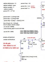
I am having trouble with the relationships in my commands. Depending on the number of samples, a function of time, I can get THD results from .000014% to .23%
Left of the fundamental depends somewhat on number of samples, which I also do not understand.
In the View for the FFT, the FFT size is set to match the fft parameter.
I know on the bench, I can measure around .003% 1K @ 5W. ( 60W amplifier) So it is a good amp, but magic!
As far as tweaking the schematic, I believe the trends are correct, but the values are unbelievable to both extremes. Curious, short runs are higher, but much longer, like 5000 cycles, are also higher distortion. What am I not understanding here?
Attachments
I would like to see something on measuring amplifier phase margin. I do a bode plot, looking at the two sides of the input diff pair and see where the phase diverges in relation to zero gain. Is that correct?
Concerning the LM3886 SPICE model:
The Whitney model (which was based on the published TI model) and the Mooly model seem to behave differently with respect to the MUTE function. According to the current TI LM3886 Rev. C datasheet (link below) the behavior of the mute function is as follows:
Mute pin floating (or connected to V- through a large resistor): MUTED
Mute pin connected to V- through a small resistor (drawing more than 0.5 mA): UNMUTED
https://www.ti.com/lit/gpn/lm3886
Here is a quote from the datasheet:
"Mute Function: The muting function of the LM3886 allows the user to mute the music going into the amplifier by drawing less than 0.5 mA out of pin 8 of the device. This is accomplished as shown in the Typical Application Circuit where the resistor RM is chosen with reference to your negative supply voltage and is used in conjunction with a switch. The switch (when opened) cuts off the current flow from pin 8 to V-, thus placing the LM3886 into mute mode."
In other words, in order to unmute the amp the mute pin needs a low resistance connection to V-. If I'm reading the example circuits correctly, Mooly's model gets it right; those showing a large value resistor between M and V- should in fact mute the amplifier but do not.
This issue was discussed some time ago in another thread, where one poster confirmed that both the PSpice and TINA models show the same error.
https://www.diyaudio.com/community/...-for-lm3886-lm3875-et-all.212805/post-3026975
Apparently, TI has never gotten around to fixing their LM3886 model.
Attached is a subcircuit by Mooly from here It seems to work OK in your circuit.
This is not a new problem. This model from Mark Whitney works well and includes a nice symbol.
The Whitney model (which was based on the published TI model) and the Mooly model seem to behave differently with respect to the MUTE function. According to the current TI LM3886 Rev. C datasheet (link below) the behavior of the mute function is as follows:
Mute pin floating (or connected to V- through a large resistor): MUTED
Mute pin connected to V- through a small resistor (drawing more than 0.5 mA): UNMUTED
https://www.ti.com/lit/gpn/lm3886
Here is a quote from the datasheet:
"Mute Function: The muting function of the LM3886 allows the user to mute the music going into the amplifier by drawing less than 0.5 mA out of pin 8 of the device. This is accomplished as shown in the Typical Application Circuit where the resistor RM is chosen with reference to your negative supply voltage and is used in conjunction with a switch. The switch (when opened) cuts off the current flow from pin 8 to V-, thus placing the LM3886 into mute mode."
In other words, in order to unmute the amp the mute pin needs a low resistance connection to V-. If I'm reading the example circuits correctly, Mooly's model gets it right; those showing a large value resistor between M and V- should in fact mute the amplifier but do not.
This issue was discussed some time ago in another thread, where one poster confirmed that both the PSpice and TINA models show the same error.
https://www.diyaudio.com/community/...-for-lm3886-lm3875-et-all.212805/post-3026975
Apparently, TI has never gotten around to fixing their LM3886 model.
Last edited:
Adding to my post above (I ran past the allowable editing time) it looks like the real purpose of the LM3886 mute pin is to provide a soft start/shutdown capability. Following is a section from a LM3886 amplifier build article showing a practical delay circuit using the mute pin.
https://www.circuitbasics.com/design-hi-fi-audio-amplifier-lm3886/#The-Mute-Circuit
If the link above doesn't take you there directly, click on the link titled "The Mute Circuit."
https://www.circuitbasics.com/design-hi-fi-audio-amplifier-lm3886/#The-Mute-Circuit
If the link above doesn't take you there directly, click on the link titled "The Mute Circuit."
sorry guys, I must be doing something dumb...
I copied Mooly's B&W703 and LM3886 .asy model into my Autogenerated folder,
LTspice can find them fine but when I try to run the simulation it comes up with
I'll have a look tomorrow if you are still stuck.
The LM3886 issues are great learning exercise, even if I doubt that I'll ever actually use it.
-The mute function seems pretty clear from the "equivalent schematic" in the data sheet. The mute input switches the IPS LTP CCS from the LTP that carries audio to an LTP that does not, so that DC values are maintained while the audio is disconnected. Mooly's model works quite different and disconnects the drivers from the VAS.
-Running Marks model puts the Mute pin at +22V, which is nothing like the schematic where the mute input returns to ground so it will always be a voltage <=0VDC.
-I am tempted to enter the "equivalent schematic", but that's a lot of work and of little value. What model would you use for PNP transistors on a monolithic chip since discrete PNP transistors will be quite different?
-I downloaded the Pspice and Tina models from TI and they are the same except for "Psice" and "Tina" and both have the problems Aniol ran into.
-The next problem with that model seems to a bad diode emission coefficient set to 0.01 when the valid values are 1 to 2. But fixing that just leads to other errors so I gave up trying to fix it.
- I found that putting the model and symbol in a folder with the schematic works if you change the path in the symbol selector dialog. This may be new because I think I tried and failed to do this before, without going to the application preferences. Using the autogenerated folder is problematic, especially when you have several versions of a part. Moving the LTC folder to "documents" is not much better than in "program files" because both are on the OS drive that is volatile, and not portable.
I agree that trying to fix the flawed TI LM3886 models or trying to develop one from the schematic is a lot of work with little upside. If one just follows the datasheet recommendations then they will probably get a good result. Experimentation is certainly interesting, but in a practical circuit I'm not one to second guess those who actually designed the device.
The main reason for my post (which wasn't clear at all) was to point out that the circuits using a high valued resistor between M and V- are not going to work as the simulation says they will. Those circuits will mute the output, contrary to simulation results. That would be a source of frustration for someone who wasn't aware of this error in the model.
IMO, Texas Instruments was very sloppy when they introduced their own "updated" models for some of the National Semiconductor (NS) ICs that they acquired. Another example is the LM4562 op amp; some of the TI models had convergence issues and other problems, including incorrect pin-outs. I tossed all of those in favor of the original National Semiconductor model that I downloaded from the NS site years ago. It would be interesting to test the original LM3886 model and see how it fares, but I haven't been able to find it.
Compliments to you on some great work with the LM3886 model.
There was a LM3886 subcircuit from the datasheet circuit by teemuk here year 2013 and includes the mute parts (but no over-current or over-temp).
I converted the netlist to a circuit (called a block subcircuit in LTspice). See attached. To view the circuit RtClk on the symbol and "Open Schematic.". It has all the same net labels as teemuks netlist (except for my odd changes below).
My changes are a bias resistor (R21) to alter the idle current if you want; it defaults to 44mA at 27C (with 80mA total from supply rails). Also power transistors Q16,Q19 are type NPN2 with Is=1e-10 like a MJL281. The datasheet doesn't provide the CCS values. I have tweaked some CCS values to get closer to the datasheet. Others may find better values.
Input bias current is 2.5uA and datasheet says 1uA max. This can be reduced if input transistors Q1, Q2 have a higher Beta, say 300. BTW the Beta of the default "NPNs" and "PNPs" are 100 with an Is f 1e-14 (IIRC). THD looks fairly close to the datasheet.
Attachments
Thanks Ian,There was a LM3886 subcircuit from the datasheet circuit by teemuk here year 2013 and includes the mute parts (but no over-current or over-temp).
I converted the netlist to a circuit (called a block subcircuit in LTspice). See attached. To view the circuit RtClk on the symbol and "Open Schematic.". It has all the same net labels as teemuks netlist (except for my odd changes below).
My changes are a bias resistor (R21) to alter the idle current if you want; it defaults to 44mA at 27C (with 80mA total from supply rails). Also power transistors Q16,Q19 are type NPN2 with Is=1e-10 like a MJL281. The datasheet doesn't provide the CCS values. I have tweaked some CCS values to get closer to the datasheet. Others may find better values.
Input bias current is 2.5uA and datasheet says 1uA max. This can be reduced if input transistors Q1, Q2 have a higher Beta, say 300. BTW the Beta of the default "NPNs" and "PNPs" are 100 with an Is f 1e-14 (IIRC). THD looks fairly close to the datasheet.
I managed to make this subckt work, I opened it, replaced the net file with one posted by teemuk, saved it (and locked it, I'm on mac, and otherwise every time I quit LTspice it deletes it). Then opened the .net file and created a symbol. Simple circuit (as per data sheet) gives me 0.002~% THD at 1kHz
I'll have a look tomorrow if you are still stuck.
I followed the same steps as above but I'm getting "u1:e*: Missing gain value"
the log file reads:
"Error on line 73 : e:u1:* u1:copyright u1:© u1:2000 u1:linear technology corporation. all rights reserved.
Unknown parameter "technology"
Fatal Error: u1:e*: Missing gain value"
and otherwise every time I quit LTspice it deletes it
Does this help with the unwanted deletion. This was something I found with models. Post #2273 There is an image to go with that as well.
Now right click the new Netlist and in 'Properties' select 'Read Only'. This will prevent LT from ever modifying this file.
I followed the same steps as above but I'm getting "u1:e*: Missing gain value"
I don't know. If you post your .asc file I can try and see what happens if I run it with the LM3886 model I have.
Hi Mooly,Does this help with the unwanted deletion. This was something I found with models. Post #2273 There is an image to go with that as well.
I don't know. If you post your .asc file I can try and see what happens if I run it with the LM3886 model I have.
I'm attaching the test circuit and the model +.net file,
Thanks
Attachments
That runs straight off (apart from 3 pins not connected on the IC and V3 set to zero) but maybe that is because I have that model set up anyway.
When you look in the Lib folder you should have the netlist as in the image here.
If you copy and paste the file somewhere else you can play around with it. If you right click it and open it with Notepad (do not accept the option to always use notepad to open these, do it as a one off) you will probably see the line at the top saying:
*C:\Users\Karl\Documents\LTspiceXVII\lib\LM3886v1_1\LM3886v1_1.asc
which is of course incorrect for your PC. Try changing that line using notepad and resave the file. When you are happy do it for real on the file in the Lib folder.

- Home
- Design & Build
- Software Tools
- Installing and using LTspice IV (now including LTXVII), From beginner to advanced