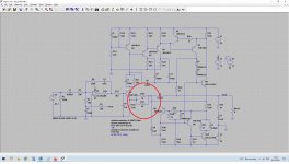
They are but the Quad 405 is a bit different to most other amps. There is another DC feedback path used to to maintain the offset to zero volts applied via R5 to the opamp.
The opamp also has its own AC feedback wrapped around just the opamp (R6 and C4).
The opamp also has its own AC feedback wrapped around just the opamp (R6 and C4).
The opamp adds a lot of voltage gain to the signal because the discrete power amp section only has a low voltage gain. Think of it as a preamp before the power amplifier.
In the Quad 405 it does more than that though, it is also used to set the DC operating point of amplifier (so there is no DC offset) by also functioning as a DC servo.
The discrete power amplifier circuit is effectively wrapped up within the opamps feedback loop for DC conditions. There is no overall AC feedback to the opamp from the power amp because of R5 and C2. These filter all the audio signal out and levae just an average DC value that the opamp uses to bias the overall amplifier.
The opamp + input is the reference and that is tied to ground (zero volts). So the DC value of the opamp output will change to a level that causes the main power amp output to also become zero volts.
Remember the output of the opamp does what is needed to keep the difference between the two inputs at zero.
The Quad 405 really is different to anything else though. Have a read at these.
Attachments
yes this is why i asked because i noticed that it differed somewhat from, what i now recognise as a fairly generic type of set up with most manufacturers of the era,but with subtle differences, on the kit i work on anyway
thanks for that though ill have another look later 🙂
thanks for that though ill have another look later 🙂
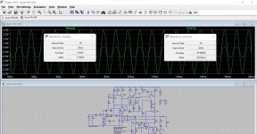
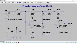
If you run the simulation you will see the power amp section (not including the opamp) has a low voltage gain.
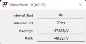
If we add a cap and resistor to remove the DC voltage then we can compare the input and output voltages directly. When we run the sim we get 2.8 volts rms out for 0.74 volts rms in. You don't have to use rms values, you can use peak or peak to peak but they are harder to see on screen and guestimate. The program does the work for you and calculate the correct rms value.
(move your cursor over where it says V(vout) at the top of the graph and then press and hold CTRL while left clicking. That will open that little window. It only does one at a time though)
So 2.8/0.74 gives a voltage gain of 3.78
The feedback network is effectively a 500 ohm (two 1k's in parallel and the 180 ohm). The gain is given by (500+180)/180 which is ta da 😉 3.78
So the sim shows that theory and practice agree.
If you look at the input signal to the opamp and the opamp output you will see we have 0.746 volts of signal coming out of the opamp for 0.0495 volts going in. Gain is 0.746/0.0495 which is 15
The opamp feedback is 330k and 22k which gives a gain of 330/22 ta da which is 15.
(and why was the gain of the first calculated using (500 +180)/180 and the gain of the opamp was just 330/22 and not (330+22)/22. That was because the opamp is configured as an inverting gain stage and the discrete power amp is configured as non inverting. Those are standard equations for calculating gain of inverting and non inverting amplifiers)
Attachments
The QUAD 405 has a very specific topology called Current Dumping. It is essentially a bridge driven by the class A input amp.
In this sense it cannot be compared to other amps like the NAD or whatever.
They all have transistors, capacitors, resistors but the 405 has a completely different circuit concept.
For instance, the 405 input opamp has a feedback cap across it.
It looks like a regular comp cap, but it is also an essential part of the feedback bridge, together with the L and a couple of resistors.
Jan
So i see this as being very simlar the the NAD set up attached here, or an i wrong with this
The opamp in the NAD is conventional and obeys all the opamp rules but it is complicated by all the additional parts around it such as the tone control networks. These are placed across the basic feedback resistor and enable the audio response to be varied as the controls are altered. You are not just altering resistance here but you are introducing capacitors which have a different impedance at different frequencies. Modifying the feedback network like this allows you to for example increase the treble or bass.

For instance, the 405 input opamp has a feedback cap across it.
It looks like a regular comp cap, but it is also an essential part of the feedback bridge, together with the L and a couple of resistors.
Jan
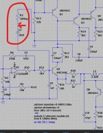
Isn't C8 the cap related to bridge balance (the 120pF)?
I've always considered the opamp as 'self contained' as far as signal processing goes and it is used to both increase input sensitivity as well as being used to set the DC operating point of the discrete section.
The cap across the opamp AC couples the opamp feedback network while allowing the overall DC feedback to be applied via R4 and R5.
IIRC Walker said that the cap served double duty as comp and as bridge element.
But I might be wrong, I'll see if I can find it.
Edit: I think you are right Karl. That 120pF cap (C8 in Walker's article) serves as Z2 in the bridge, but I think what I read was that it also compensates the 'class A' driver amp, not the opamp. Hmmm.
Jan
But I might be wrong, I'll see if I can find it.
Edit: I think you are right Karl. That 120pF cap (C8 in Walker's article) serves as Z2 in the bridge, but I think what I read was that it also compensates the 'class A' driver amp, not the opamp. Hmmm.
Jan
Last edited:
C8 is certainly wrapped around the Class A stage so it has got to play a big part in stability.
What might confuse at first (not you 🙂) is seeing all the original diagrams in those articles where they actually do draw an opamp but that really represents the discrete class A transconduction stage.
It is a fascinating design and one I puzzled long over when I was younger.
What might confuse at first (not you 🙂) is seeing all the original diagrams in those articles where they actually do draw an opamp but that really represents the discrete class A transconduction stage.
It is a fascinating design and one I puzzled long over when I was younger.
If you run the simulation you will see the power amp section (not including the opamp) has a low voltage gain.
If we add a cap and resistor to remove the DC voltage then we can compare the input and output voltages directly. When we run the sim we get 2.8 volts rms out for 0.74 volts rms in. You don't have to use rms values, you can use peak or peak to peak but they are harder to see on screen and guestimate. The program does the work for you and calculate the correct rms value.
(move your cursor over where it says V(vout) at the top of the graph and then press and hold CTRL while left clicking. That will open that little window. It only does one at a time though)
So 2.8/0.74 gives a voltage gain of 3.78
The feedback network is effectively a 500 ohm (two 1k's in parallel and the 180 ohm). The gain is given by (500+180)/180 which is ta da 😉 3.78
So the sim shows that theory and practice agree.
If you look at the input signal to the opamp and the opamp output you will see we have 0.746 volts of signal coming out of the opamp for 0.0495 volts going in. Gain is 0.746/0.0495 which is 15
The opamp feedback is 330k and 22k which gives a gain of 330/22 ta da which is 15.
(and why was the gain of the first calculated using (500 +180)/180 and the gain of the opamp was just 330/22 and not (330+22)/22. That was because the opamp is configured as an inverting gain stage and the discrete power amp is configured as non inverting. Those are standard equations for calculating gain of inverting and non inverting amplifiers)
in the opamp attached there are references to ground that are both + and - why is that?/how does that work?
Attachments
Op amps have both inverting (-) and non-inverting (+) inputs, neither of which is nominally tied to ground but which are referenced to signal ground. This is a pretty fundamental issue, so I think you might benefit from learning about basic op amp operation and configurations before trying to understand how an op amp is used in a complex circuit. Here is a link that might help you get started.
https://www.electronics-tutorials.ws/opamp/opamp_1.html
I hope this is helpful.
https://www.electronics-tutorials.ws/opamp/opamp_1.html
I hope this is helpful.
Isn't C8 the cap related to bridge balance (the 120pF)?
I've always considered the opamp as 'self contained' as far as signal processing goes and it is used to both increase input sensitivity as well as being used to set the DC operating point of the discrete section.
The cap across the opamp AC couples the opamp feedback network while allowing the overall DC feedback to be applied via R4 and R5.
So after researching, this is the internals to the op amp in the nad(attached) it an NJM 2043
Attachments
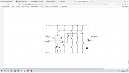
You really don't need to be concerned about the internal circuit of an op amp unless the issue of FET vs. BJT input is an issue to you. Most of the time it is not, and you can therefore consider the op amp to be a "black box" that behaves as described in the link I provided.
There is no need to over-complicate the analysis of the circuit.
There is no need to over-complicate the analysis of the circuit.
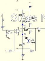
Does anyone have a good sharable LTspice file for op-amp plus booster output stage headphone amplifier? Something like a op-amp plus Class A or AB booster or Graham Slee Solo schematic or Beyerdynamic A1 schematic?
Particularly a sharable LTspice file well setup to look at stability?
The reason I ask is that my Graham Slee Solo Clone works just fine with NE5534 but it killed an OPA1611A in a few short seconds and then it killed an OPA228 in a few short seconds. Put the NE5534 back in and it plays happily. Fortunately the headphones are fine and there was no audible output. Symptoms were no audible output and hot op-amp very quickly. (Very high frequency oscillation?)
So I was wondering if an LTSpice simulation might possibly shed light on what happened. The attached schematic was "edited" to match the board. For whatever reason they used A42/A92, different resistor values and a configuration more like the newest versions of the Solo. (While the schematic, before editing, was more like older versions of the Solo.)
While it might be a lost cause I thought I would see if there is a good sharable LTspice starting point. Of course I will need NE5534, OPA1611A and OPA228 models. Also I thought the LTspice thread would be a good place to get suggestions on what likely went wrong.
Attachments
You really don't need to be concerned about the internal circuit of an op amp unless the issue of FET vs. BJT input is an issue to you. Most of the time it is not, and you can therefore consider the op amp to be a "black box" that behaves as described in the link I provided.
There is no need to over-complicate the analysis of the circuit.
i am just curious to know what things look like inside as well as anything else so i can compare it to other makes etc.
- Home
- Design & Build
- Software Tools
- Installing and using LTspice IV (now including LTXVII), From beginner to advanced