Does anyone have a good sharable LTspice file for op-amp plus booster output stage headphone amplifier? Something like a op-amp plus Class A or AB booster
WHAMMY (designed by the preamp guy at Pass Labs, and sold in the diyAudio Store) is an opamp plus class A booster output stage. Maybe you could visit their Forum thread and ask whether anyone is willing to share their LTSPICE file.
"WHAMMY" Pass DIY headphone amp guide
So after researching, this is the internals to the op amp in the nad(attached) it an NJM 2043
That is typical in outline of many opamps. We can even make our own in LT with as few as three transistors (haven't tried but I think we could).
If you want a sim of the insides of a real opamp then go to your LTspice folder in Documents and look at the Examples folder. In there is a folder called 'Educational' where there is a 741 (probably the best known opamp of all time).
If you want you can save the sim again somewhere else with a new name to preserve the original and you can have play.
Run the simulation and see if you can figure out how the gain is set. Remember the Quad earlier and I described how the gain was calculated.
Attachments

i am just curious to know what things look like inside as well as anything else so i can compare it to other makes etc.
But it is not how it looks inside. The actual inside has many more parts than is shown. As is usual, these are only 'simplified internal circuits' to show general topology. But even an LTspice model most of the times has more parts than this.
You normally have to know a very few things only for evaluating circuits with opamps. The most simple is that the voltage between the input pins is the output voltage divided by the open loop gain. Since the open loop gain is very, very high, a rule of thumb is that the voltage between the input pins is zero, so they can be considered being at the same voltage. The other important thing is that the inputs don't require input currents (for a 1st level analysis).
Look at Mooly's example above. The input voltage is connected to one input pin of the opamp. From what I just said, you know that the other input pin has the same voltage. Then it is only the ratio of two resistors that sets Vout.
Easy as pie ;-)
Jan
Last edited:
i am just curious to know what things look like inside as well as anything else so i can compare it to other makes etc.
But it is not how it looks inside. The actual inside has many more parts than is shown. As is usual, these are only 'simplified internal circuits' to show general topology. ...
Jan is spot on, but, there is one way to get a true'r insight of the actual contents of these (not the so modern) opamp's. Get some early 714 and 709, or alike, datasheets in those days the world was a simpler, more honest, place (I guess).
Last edited:
Some engineers are employed to investigate patent infringements. They use sulphuric acid (sp?) to dissolve the epoxy around a chip and a microscope to reverse engineer the circuit.
I know one, I can ask for his rate sheet ;-)
Jan
I know one, I can ask for his rate sheet ;-)
Jan
@poundy: trying to educate yourself by studying the insides of opamps is about the worst method you can choose.
There is so much in opamps that is not directly related to the signal path, but to biasing, current sourcing, temp compensation, current limiting etc that only the experts can see the forest through the trees.
Study a simple 3-transistor amplifier circuit and make sure you absolutely understand the relevance of every part, why it is there, why it has its value, how it impacts the resulting output. Then move on.
That's the fastest way to enlightenment.
And it takes effort and real study. Sorry about that.
Jan
Data sheets used to include a simplified equivalent schematic and some still do, but others want to keep their circuit secret. Some have schematics with obvious errors, perhaps to throw copy cats off. They know that it's important to sell their product to knowledgeable designers who do care very much what's inside because it tells them much more about what behavior to expect than simply a list of parameters. For that reason National Semi used to publish theory of operation of their chips. Counterfeit copies were not a big problem in those days.
Jan is spot on, but, there is one way to get a true'r insight of the actual contents of these (not the so modern) opamp's. Get some early 714 and 709, or alike, datasheets in those days the world was a simpler, more honest, place (I guess).
Maybe this will help as a educational tool
Ampli-op 741 discret format XL - Elektor
https://www.elektor.fr/media/catalo...6cf/x/l/xl741_discrete_opamp_kit_contents.jpg
But the amp is not a modern one they are to complicated to do a disassembly and rebuild like this.
LTspice Working Paper for Tube-Amplifier Simulation for free download,
75 pages incl. some tube-amplifier LTspice examples. This Working Paper is a supplement on how simulate tube amplifiers with LTspice.
DIY AUDIOPHILE TUBE ELECTRONIC | "es bizeli zuesatzliche infos fuer de audio rohre chlutteri" Swiss-German translation ;-) Sorry, the PDF file is too big for upload into diyAudio
I wrote this document mainly for myself, because I’m an amateur user of the nice LTspice software. In the past I always fail with the transformer simulation and was not sure how good the tube models are, which I found on the web.
The document is simple and self-explain. Sorry, I have no time to answer questions to my working paper; first my English is very bad and take me lot of time to answer questions. Second, I have so many not finished tube projects on my bench
Hi All
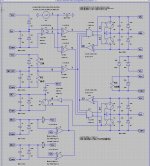
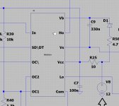
I have a model of a gatedriver for mosfets, I did use it in class d, there is a problem, the supply of 12 volts for the ic IRS20124s needs to be connected to COM for reference to inputs and negative rail voltage, but when I do simulating with dual supply,s it does not work, when I connect 12 volts to ground it does work.
This is not right, normally I need to reference to Vss, like the other ic,s, the ic can be used for double supply, I have others who do work fine with Com or Vss to -V reference.
Maybe someone can see in schematic block there is something wrong.
thanks.
Attachments
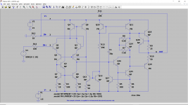
Can someone tell me which good audio op-amps have accurate LTSPICE models?
I am simulating a variety of HPA in LTSPICE and would like to know which op-amps models are particularly accurate and trustworthy. (See attached example simulation.)
I am simulating a variety of HPA in LTSPICE and would like to know which op-amps models are particularly accurate and trustworthy. (See attached example simulation.)
Attachments
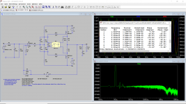
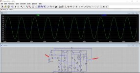
This is a distortion plot I've just this minute done in another thread:
12 opamps chained - measurements
What you can assume is that the output stage of the Whammy in your sim is working OK and that any distortion will be mostly down to the opamp used. I assume the output stage is biased to the correct intended current... it should be even allowing for different models with a bias scheme like you have.
I saw that post. Yes, that seems to be the problem.
Do you know of any good audio opamps where the distortion is modeled?
Do you know of any good audio opamps where the distortion is modeled?
I'm afraid I don't, its not something I've ever looked into tbh. Your best bet might be to look at real world test data such as from Samuel Groners 'Op Amp Distortion' where FFT plots and so on are shown for lots of popular devices.
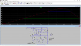
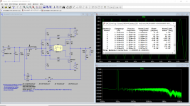
Attached is with the OPA1611 model from Ti. Distortion is zero so it appears that no attempt is made to model distortion. (And distortion is not listed as a model feature in the model comment lines.) Presumably it is simply too difficult for SPICE models to model opamp distortion? Too much modeling effort for the manufacturer and/or simulation speed issues?
I assume then LTSPICE can be used to approximate and tune the rest of the circuit and the datasheet distortion curves are used as the first reference for what the opamp will do.
I guess next I can look at a discrete front end or discrete opamp for the HPA to further the simulations. Any suggestions for a good but not overly complex starter discrete opamp that I could use in my HPA simulations?
Attachments
I wrote this document mainly for myself, because I’m an amateur user of the nice LTspice software. In the past I always fail with the transformer simulation and was not sure how good the tube models are, which I found on the web.
I've found the Ayumi models to be very good. His generic models aren't compatible with LTspice syntax but diyAudio member kevinkr has gone to the trouble of preparing a library that works in LTspice. See link below; the file that you want is Ayumi_LTspice.zip, updated June 29, 2018.
Vacuum Tube SPICE Models
Last edited:
The opamp adds a lot of voltage gain to the signal because the discrete power amp section only has a low voltage gain. Think of it as a preamp before the power amplifier.
In the Quad 405 it does more than that though, it is also used to set the DC operating point of amplifier (so there is no DC offset) by also functioning as a DC servo.
The discrete power amplifier circuit is effectively wrapped up within the opamps feedback loop for DC conditions. There is no overall AC feedback to the opamp from the power amp because of R5 and C2. These filter all the audio signal out and levae just an average DC value that the opamp uses to bias the overall amplifier.
The opamp + input is the reference and that is tied to ground (zero volts). So the DC value of the opamp output will change to a level that causes the main power amp output to also become zero volts.
Remember the output of the opamp does what is needed to keep the difference between the two inputs at zero.
The Quad 405 really is different to anything else though. Have a read at these.
Does anyone know what's the purpose of the L2 and L1 in the current dumping circuit?
- Home
- Design & Build
- Software Tools
- Installing and using LTspice IV (now including LTXVII), From beginner to advanced