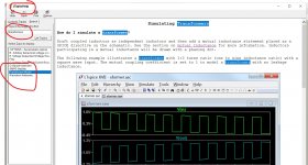
@Poundy - I think you'll find 'Vin' is simply a label to see the value of the voltage in the circuit at that point, it's not an input into the circuit (that's V3). If you run the simulation, then click on Vin you'll see it plotted vs. time. You can add similar labels almost anywhere you want - it can make it easier to keep track of things when you're working with a schematic.
A slightly related related question @Mooly if I may - I'm trying to simulate one of the group buy PS circuits from 'Prasi' (CRC Power Supply (Class A amplifier) ; the schematic in post #82), and am wondering what the best way to simulate the AC1 & AC2 supplies is ?
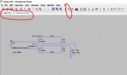
Specifically, I'm looking at a toroidal transformer, 1X 240VAC / 2X 35VAC, 160VA, ca. 8% regulation, with one secondary as AC1, and the other as AC2.
Would you model AC1 & AC2 in a similar way to V3 in your example above ? or go a step further back, and model the transformer as well ? I suspect the former, but am then wondering how best to determine the 'parasitic series resistance', is that just measured ?
A slightly related related question @Mooly if I may - I'm trying to simulate one of the group buy PS circuits from 'Prasi' (CRC Power Supply (Class A amplifier) ; the schematic in post #82), and am wondering what the best way to simulate the AC1 & AC2 supplies is ?
Specifically, I'm looking at a toroidal transformer, 1X 240VAC / 2X 35VAC, 160VA, ca. 8% regulation, with one secondary as AC1, and the other as AC2.
Would you model AC1 & AC2 in a similar way to V3 in your example above ? or go a step further back, and model the transformer as well ? I suspect the former, but am then wondering how best to determine the 'parasitic series resistance', is that just measured ?
Transformers are not easy to model tbh. I would say you could just use a floating voltage source for those, it will get you 90% of the way there.
Series resistance is a bit of a guestimate. You will need to work out what the DC railss might reduce by at full load for the real transformer and then pick a series R to mimic that same fall.
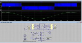
Just a doodle. Try this although I haven't worked out the percentages exactly. It looks in the right ballpark as the load is varied. The 10ks just ground reference it.
Series resistance is a bit of a guestimate. You will need to work out what the DC railss might reduce by at full load for the real transformer and then pick a series R to mimic that same fall.
Just a doodle. Try this although I haven't worked out the percentages exactly. It looks in the right ballpark as the load is varied. The 10ks just ground reference it.
Attachments
so is vin(ac1) ac voltage?
is this applied in all amplifiers in the real world? or just the sim
if so where would that be for example on the attached
In the sim you can call it and label it whatever you want.
In the real world Vin would be either the left or right channel output from a source component such as a CD player or cartridge.
In your NAD diagram you would apply the simulation voltage source to whichever bit of the circuit you were modelling.
So if you were modelling the power amp you would apply it to the point marked X.
If you were modelling the Phono stage you would apply it where it says Phono and so on.
You could also model the whole amplifier, everything, and have multiple voltage sources applied to every input simulating CD, Tuner, Phono etc. You would then have the sim set up with the appropriate switches and signal paths in place for the input you wanted to simulate.
Cheers Karl - my concern arose from trying a simple sine voltage source, and monitoring the initial inrush current (actually to check I'd ordered the right diodes). The sim appears to work fine, but varying the parasitic series resistance has a major impact on the inrush current... so I started questioning the approach I was using.
View attachment NEW PSU.asc
I'll try your 'doodle' approach....
View attachment NEW PSU.asc
I'll try your 'doodle' approach....
Parasitics do make a MASSIVE difference. You'll see that in your sim. The real worls transformer would be sure to limit initial current peaks even more I think during first couple of cycles.
You can copy and paste my sim into yours.
1/ Open both.
2/ Use copy to drag a box around the part you want to copy.
3/ Click the other sim to display it and just place the copied portion onto the sheet.
4/ Delete any duplicate or conflicting .op commands. Just run it to see.
1/ Open both.
2/ Use copy to drag a box around the part you want to copy.
3/ Click the other sim to display it and just place the copied portion onto the sheet.
4/ Delete any duplicate or conflicting .op commands. Just run it to see.
Attachments
Maybe this helps, earlier I showed how to create a 'simulated' resistor
see Installing and using LTspice IV (now including LTXVII). From beginner to advanced.
Resistors can be used ad switches
1uOhm = On
1GOhm = Off
So I botched this together
There is an oscillator V2 generating v(va) that is used as the control voltage for the switches.
There is a voltage V1 to be 'transported' by the floating capacitor C1
Just run it and see how it functions.
P.s. I could not run/test the uploaded file due to the fact that I did not have the needed models
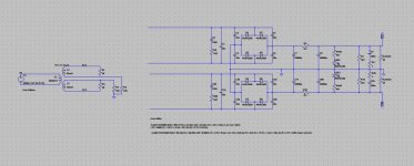
I was forgetten to mention that I had already simulate this with LTspice own switches models, so no need for switched resistors. I do use two three level in BTL mode and shift one 90 degree to get 5 level.
That way everything looks good, mine idea was to use real gatedriver models to see how to do it right way or if it does work, also curiosity, like the mars rover..
Attachments

Last edited:
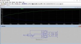
The transformer version certainly seems to provide much more realistic values, esp. for inrush currents etc., but I'm struggling to understand the R1 & R2 in your transformer model; are these modelling 'losses' or are they just to simulate the transformer on its own ? I notice R1 is also apparently open at one end (?).
Also, how did you arrive at the inductance & series resistance values ? from a known example ? or calculated / estimated ?
Also, how did you arrive at the inductance & series resistance values ? from a known example ? or calculated / estimated ?
They were just dummy loads when I was playing around 🙂 they draw around 1.9 A @ 34 volt so around close to 130va loading in total.
I was just comparing one side to the other with and without load tbh.
Edit... guestimated and trial and error for the values. It was more how it behaved that I was aiming for.
I was just comparing one side to the other with and without load tbh.
Edit... guestimated and trial and error for the values. It was more how it behaved that I was aiming for.
Attachments
I guess that'll be the same 18R's I was using at the other side of the PS... and lifting in the same way... for the same reason... sorry, will try and remember to engage brain next time !
sorry, will try and remember to engage brain next time !I was forgetten to mention that I had already simulate this with LTspice own switches models, so no need for switched resistors. I do use two three level in BTL mode and shift one 90 degree to get 5 level.
That way everything looks good, mine idea was to use real gatedriver models to see how to do it right way or if it does work, also curiosity, like the mars rover..
Looks good, I imagine that it now works?
One note, remember that any/every point in a simulation at all times must connect to ground. if not the simulation will fail. I did solve it by adding some leakage capacitors to ground.
P.s. the switches as build in are actually equivalent/equal to the ones that I used.
Extra resistors are R1 and R5 see Installing and using LTspice IV (now including LTXVII). From beginner to advanced.
Last edited:
Hi
I have never problems with these ltspice simple models like the switches then it go well.
I have a lot of problems, (still) with floating stuff, not the ground referenced ones but the upper floating mosfets.
So your idea of put every leakage capacitors to ground. LTspice has quite problems with this kind of floating circuits, except when
use the simple own models like switches in stead of mosfet models.
Can I also use 10 Meg resistors to ground as help for proper simulations?
go try .options cshunt=1e-15
Maybe this solve things.
Thanks for the tips.
Last edited:
Dit not work, Cshunt fails, I have now done 10Meg resistors on every floating node, it does sim now, but LTspice has for shure problems.
Looks good, I imagine that it now works?
One note, remember that any/every point in a simulation at all times must connect to ground. if not the simulation will fail. I did solve it by adding some leakage capacitors to ground.
P.s. the switches as build in are actually equivalent/equal to the ones that I used.
Extra resistors are R1 and R5 see Installing and using LTspice IV (now including LTXVII). From beginner to advanced.
Here I have the schematic who fails or sometimes does work, strange is yesterday it did so well, today it just fails, maybe I have software who intervene with LTspice?.
I have the models uses included, little curious what I do wrong or if LTspice has trouble simulation these kind of circuits..
Thanks
regards
Attachments
Hi
I have never problems with these ltspice simple models like the switches then it go well.
I have a lot of problems, (still) with floating stuff, not the ground referenced ones but the upper floating mosfets.
So your idea of put every leakage capacitors to ground. LTspice has quite problems with this kind of floating circuits, except when
use the simple own models like switches in stead of mosfet models.
Can I also use 10 Meg resistors to ground as help for proper simulations?
go try .options cshunt=1e-15
Maybe this solve things.
Thanks for the tips.
As far as I know it is the Gmin parameter (see Tools|Control panel|Spice) that determines the minimum conductivity from every PN junction to ground. Playing with that often gets it going as the PN junctions are normally quite nonlinear.
Jan
Last edited:
Hi Jan
I have tryed that already, I have also such a strange behavior that I did succesfully sim one of the circuits with the models mention and the next day it did not, maybe there is software installed who does interact with LTspice.
Al is mine idea that the models who most of the time are for Tina does not work wel, maybe there is something in it I do not understand well, who is true.
I can succesfully simulate normal behavior models like switches, but then I do not now how it does with real time circuits.
Plecs and simulink is even more complicated.
Can try with pc on save mode to see what happens.
If you mistrust the model it is best to test it in a stand-alone test circuit, not in your application circuit.
In these cases you want to check just the model nothing else. Just the chip, power sources and input/output.
Divide and conquer.
Jan
In these cases you want to check just the model nothing else. Just the chip, power sources and input/output.
Divide and conquer.
Jan
I did already earlyer, it did fine.
I does now simulate, have change gmin and abstol to 1e-008
change reltol to 0.003 set Noopiter and skip gmin stepping on.
and use solver normal with trapezoidal.
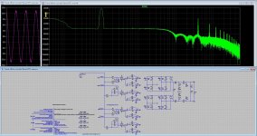
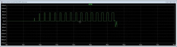
Can play more with that, it sims now without errors and other strange behavoirs, output looks good. Cshunt did need to be removed, with it ni simulations, it just hangs. see on pic with garbage on end where it hangs.
These kind of sims with flying cap or other floating stuff does not work properly, I have made it some easyer for ltspice to use single and not btl because that is flauwekul afcourse.
Then still it is slow, but usable to see more then with behavior models.. You see a nice sinus and three level output, so the models do work.
regards
I does now simulate, have change gmin and abstol to 1e-008
change reltol to 0.003 set Noopiter and skip gmin stepping on.
and use solver normal with trapezoidal.
Can play more with that, it sims now without errors and other strange behavoirs, output looks good. Cshunt did need to be removed, with it ni simulations, it just hangs. see on pic with garbage on end where it hangs.
These kind of sims with flying cap or other floating stuff does not work properly, I have made it some easyer for ltspice to use single and not btl because that is flauwekul afcourse.
Then still it is slow, but usable to see more then with behavior models.. You see a nice sinus and three level output, so the models do work.
regards
Attachments
Last edited:
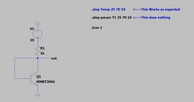
Hi, me again, I have run in to a problem simulating the temperature dependency of an MMBT3904 and would like to ask for some help.
When I change the global Temperature with .step Temp 25 70 10 It shows the expected behavior of changing Vbe. If I change it just for the Part with .step param T1 25 70 10 an set Value2 to Temp = {T1} for the device nothing happens. Does annyone know if this is intended? And is there a way around this?
I made a minnimum working example in LTspice and attached it to this post. Here is the used Model:
***********************************************************
*
* MMBT3904
*
* Nexperia
*
* Switching NPN Transistor
* IC = 200 mA
* VCEO = 40 V
* hFE = 100 - 300 @ 1V/10mA
*
*
*
*
* Package pinning does not match Spice model pinning.
* Package: SOT 23
*
* Package Pin 1: Base
* Package Pin 2: Emitter
* Package Pin 3: Collector
*
*
* Extraction date (week/year): 25/2014
* Spicemodel includes temperature dependency
*
**********************************************************
*#
.SUBCKT MMBT3904 1 2 3
Q1 1 2 3 MAIN
D1 2 1 DIODE
*
* Diode D1 is dedicated to improve modeling in reverse
* mode of operation and does not reflect a physical device.
*
.MODEL MAIN NPN
+ IS = 2.612E-015
+ NF = 1.005
+ ISE = 2.958E-015
+ NE = 1.533
+ BF = 169
+ IKF = 0.08351
+ VAF = 53.92
+ NR = 0.9982
+ ISC = 3.177E-016
+ NC = 1.094
+ BR = 2.107
+ IKR = 0.5
+ VAR = 100
+ RB = 114
+ IRB = 0.001
+ RBM = 6.2
+ RE = 0.04181
+ RC = 0.9576
+ XTB = 1.522
+ EG = 1.11
+ XTI = 4.633
+ CJE = 1.032E-011
+ VJE = 0.6333
+ MJE = 0.2056
+ TF = 3.55E-010
+ XTF = 10
+ VTF = 2
+ ITF = 0.3
+ PTF = 0
+ CJC = 3.181E-012
+ VJC = 0.8831
+ MJC = 0.3242
+ XCJC = 1
+ TR = 1.45E-007
+ CJS = 0
+ VJS = 0.75
+ MJS = 0.333
+ FC = 0.78
.MODEL DIODE D
+ IS = 1.82E-013
+ N = 1.042
+ BV = 1000
+ IBV = 0.001
+ RS = 380.9
+ CJO = 0
+ VJ = 1
+ M = 0.5
+ FC = 0
+ TT = 0
+ EG = 1.11
+ XTI = 3
.ENDS
*
Attachments
- Home
- Design & Build
- Software Tools
- Installing and using LTspice IV (now including LTXVII), From beginner to advanced