I've tried all opamps that you suggest in this application and had the greatest success with the OPA1611. IME it sits just below or equal to the AD797 in most respects but I've never had the stability problems with it that I and others have had with the AD797.
Very interesting chip. Is there an Ltspice model of it?
What I did was to use what l learned here, starting from the .sub file and following the AD tutorial to what to an .asy file. But I can't get it to work as the AD797 did.
What model did you use for your OPA?
Is there something in OPA models that make it different?
Soekris DAC PSU
Hi All,
I would use superreg (2 x positive 5V and 1X negative 5V) for DAC from Soekris. Do you have experience with that?
Soekris Audio ApS, Products dam1941
Can you please advise me which diodes and smoothing capacitor to use for the best performance? Current consumption is around +-80mA and +500mA. I would use separate windings, rectifiers and smoothing capacitor for each superreg.
Thanks
The way to quickly check is, is as follows.
Set up a simple opamp circuit with the OPA134. +/-15V supply, output connected to inv input. Put a 1kHz 1V at the noninv input, and if the output also shows 1V 1kHz, your model is fine.
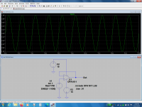
OK, I think I did what was required. And this is not what I should get at the output.
Something I'm doing, quite likely, is completely wrong.
No doubt someone can explain what it is.
Attachments
Since we don't have your OPA134 symbol nor your subckt file on our computers we can't run that sim.
Run it with an AD711 to see if the circuit is OK.
Then run it with the OPA134 to see if the subckt is OK.
These are all standard debugging steps.
But you moved again the subject I think, to the OPA1611.
Jan
Run it with an AD711 to see if the circuit is OK.
Then run it with the OPA134 to see if the subckt is OK.
These are all standard debugging steps.
But you moved again the subject I think, to the OPA1611.
Jan
Sorry, if I called the asc file OPA1611, instead of OPA134 or any other.
As I don't have the AD711 model I can't use it. So I used a file we have been discussing recently and that supposedly you all might have: AD825.
Using that on the model shows a perfect sinusoidal.
The model does work, the OPAs don't.
As I don't have the AD711 model I can't use it. So I used a file we have been discussing recently and that supposedly you all might have: AD825.
Using that on the model shows a perfect sinusoidal.
The model does work, the OPAs don't.
Attachments
Then you have made some mistake importing the OPA134 model or in the circuit.
I saw in the earlier .asc you send that it appeared you had connected Vee to the output. Maybe check the node labels on the auto-created symbol for the OPA134.
Jan
I saw in the earlier .asc you send that it appeared you had connected Vee to the output. Maybe check the node labels on the auto-created symbol for the OPA134.
Jan
Last edited:
Bill, I'm sure it does. Your method of importing a model is correct of course.
I find it easier to make a symbol for each imported model or .subckt, but that's just personal preference. Ways to skin a cat.
Jan
I find it easier to make a symbol for each imported model or .subckt, but that's just personal preference. Ways to skin a cat.
Jan
Me doing mistakes is very much possible. Distracted as I am.
But I just sent an asc file that does work. Tried with different opamps, including the AD825, and it generates the 1000Hz it should.
Now the question is where's the error (which could be mine), importing the OPAs, because it just happened with two. I'm not doing anything different from what I learnt with the others.
Please look at the zipped OPA1611 file I sent above, and tell me if the procedure should be different. I got it from TI, the same as the OPA134.
Just now I did repeat procedure all over again, and I'm getting the same results.
As mentioned before, you keep on sending .asc files without your symbols, so it won't work at anyone's PC but yours.
Looking at the .asc it appears that you connected the output, if that is the middle pin, to Vee. But again, since we don't have your symbol, we can't say for sure what is wrong.
Jan
Looking at the .asc it appears that you connected the output, if that is the middle pin, to Vee. But again, since we don't have your symbol, we can't say for sure what is wrong.
Jan
Attachments
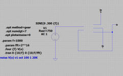
Jan, I think I'm doing things right and the DIAudio program is chaning them.
Now I am enclosing an image of the generator I'm sending, which is different from the one you are getting. Also enclosing another file with the part data I'm using to make the model.
Believe me I'm doing the best I can and trying to follow your instructions. That's why I do no understand what's happening.
Attachments
Carlos, the symbol is NOT part of your schematic! LTspice reads it in and places it when you open the schematic. It then looks for the subcrkt the symbol points to, and tries to open that.
When you send me your .asc and I open it, MY LTspice tries to open the symbol, doesn't find it (because it is on YOUR computer) so I cannot run the schematic.
When you send your .asc to others, and it has symbols and subcrkts that are not part of the normal LTspice install, YOU must send all of them with your schematic.
Of course all of this is explained in the Help file that nobody reads. So we go around and around, going actually nowhere.
I need more popcorn.
Jan
Last edited:
Please re-read # 2117, 3rd sentence.
A symbol is the thing that ends with .asy .
The circuit is the circuit file that has the line in it;
.subckt bla bla, or
.model bla bla.
These circuit files can be .txt, .lib, .cir , whatever.
The smart way to send it all to someone to check it out is to zip the .asc and any .asy and .cir etc that are needed to run it, and which YOU made and are not in the normal LTspice installation, and send the zip.
Jan
Last edited:
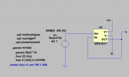
carlmart sent me this private message: "Where did you get the OPA1611 symbol? "
I prefer that this issue be discussed on the public forum so I will answer here.
First off, I use LTspice IV, not the later version. If what I do doesn't work on the later version, someone else will have to provide guidance there.
From the schematic in the top toolbar of LTspice IV select Edit and then Component. Then select [Opamps] and click on OK. Scroll all the way to the right, select opamp2 and click OK. The symbol will be routed to the schematic - click to place it where you want it.
As long as the op amp model pin configuration matches the symbol pin configuration this works fine. I can't recall ever finding an op amp model that didn't match the opamp2 symbol.
The run I did earlier in this thread used the TI model for the OPA1611 linked earlier in this thread. The OPA1611 model runs fine and I see nothing unusual about how LTspice handles it.
Attachments
Last edited:
To clarify a bit more on the internal workings of LTspice, that might help:
If you look at the .asc with a word processor, you see what is known as 'the netlist'. It is a list of all parts you placed on the schematic, their connections, and their values. The parts are all represented by a 'symbol'. For resistors, the value of the symbol (called 'symattr') is the resistance in ohms; for an opamp, the value is the name of the opamp and when you load the schematic, LTspice uses the 'value' of the symbol to pick the part up from its store of parts. Resistors for instance are in the LTspice own sym and lib files so no problem to find it.
However, if you import say an opamp from outside, you must make sure that the symbol points to the model file where you stored it on your computer. It also means that sending your .asc to someone without that external sym and lib file is useless because LTspice will not find that on the computer of whoever you send it to. In such a case, you must send any external lib files and their symbols with the .asc.
Below are some relevant .asc snippets.
WIRE 240 -240 160 -240
WIRE 160 -224 160 -240
WIRE -288 -192 -288 -240
WIRE -272 -192 -288 -192
WIRE 0 -192 -192 -192
WIRE -976 -144 -976 -384
WIRE -592 -80 -592 -176
WIRE -576 -80 -592 -80
WIRE -496 -80 -512 -80
WIRE -384 -80 -384 -320
WIRE -384 -80 -416 -80
WIRE 64 -64 64 -240
SYMBOL res -352 416 R90 ; the 'R90' does not mean R90, it means: rotate the symbol 90 degrees when placing.
WINDOW 0 0 56 VBottom 2
WINDOW 3 32 56 VTop 2
SYMATTR InstName R1
SYMATTR Value 1k
SYMBOL npn2 -528 272 M0
SYMATTR InstName Q1
SYMBOL Opamps\\AD8031 -176 368 M0
WINDOW 0 75 183 Left 2
WINDOW 3 35 159 Left 2
SYMATTR InstName U3
SYMBOL res -608 496 R0
SYMATTR InstName ebot
SYMATTR Value 10
SYMBOL res 176 512 R0
SYMATTR InstName R9
SYMATTR Value 10k
Bottom line: LTspice does not store the schematic as a picture or something, but as a 'menu' on how to recreate it. It picks up all parts and wirings from the menu and re-constructs the schematic every time you open it. But you must make sure that the poor program can find all those bits and pieces!
Jan
Last edited:
@ Bill_P: In case you use an LTspice internal symbol like opamp2, as you did, then you only need to send the lib file with the .asc for someone to be able to use it, I guess, because the opamp2 symbol would be in any standard LTspice install.
Jan
Jan
To continue this workshop ;-)
A symbol has much of the same syntax as a regular .asc schematic. If you open a .asy with Wordpad, you see something like the list below. I will insert comments between blocks.
Version 4
SymbolType BLOCK
RECTANGLE Normal -48 -56 48 56 // this is the familiar yellow block
WINDOW 0 0 -56 Bottom 2
WINDOW 3 0 56 Top 2
SYMATTR Prefix X // it's a subcircuit, not a model
SYMATTR Value AD797B // name of the symbol
SYMATTR ModelFile C:\Users\jandi\Downloads\ad797b.cir //the all-important path to the subcircuit file. You can edit this, but if LTspice cannot find that file in the specified folder, you get an error. That is also the reason that the .asc will not work for someone else if that subckt file is not at that exact place, which it will not be, unless it is a component that is part of the normal LTspice installation.
// following are the pins on the symbol. There are two important parameters: the pin name which is what is shown on the schematic, like '+i'. Then the Spiceorder, which is the order of this pin in the subcircuit .subckt line. So, in the .subckt, the first pin on the line can be named anything, like '22' or 'inverting input', but it 'connects' to the pin on the symbol that we see on the schematic called '+i'. This naming can be changed if you edit the symbol. The LEFT or RIGHT specify where the pin is on the yellow block symbol.
PIN -48 -32 LEFT 8
PINATTR PinName +i
PINATTR SpiceOrder 1
PIN -48 0 LEFT 8
PINATTR PinName -i
PINATTR SpiceOrder 2
PIN 48 -32 RIGHT 8
PINATTR PinName Vc
PINATTR SpiceOrder 3
PIN 48 32 RIGHT 8
PINATTR PinName Ve
PINATTR SpiceOrder 4
PIN 48 0 RIGHT 8
PINATTR PinName O
PINATTR SpiceOrder 5
PIN -48 32 LEFT 8
PINATTR PinName Cc
PINATTR SpiceOrder 6
Jan
Last edited:
- Home
- Design & Build
- Software Tools
- Installing and using LTspice IV (now including LTXVII), From beginner to advanced