Show how you create the triangle
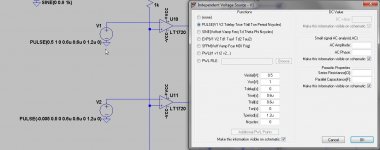
Like this, using voltage source.
PULSE(-0.005 0.5 0 0.6u 0.6u 0 1.2u 0) -0.005 is for setup only, no further importance.
regards
Attachments
Try this, you will be happy (again 🙂) because it will improve your life 🙂
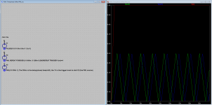
For all others, this is a PWL-voltage-source that starts at a adjustable delay time and then repeats forever, it offers the (almost) same functionality as phase shift in a SINE-voltage source.
For all others, this is a PWL-voltage-source that starts at a adjustable delay time and then repeats forever, it offers the (almost) same functionality as phase shift in a SINE-voltage source.
Attachments
Last edited:
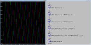
P.s. the 'TRIGGER' modifier can also be used with a PULSE-voltage-source
Line: PULSE(0 0.5 0 0.6u 0.6u 0 1.2u 0) TRIGGER V(vt2)>=300n
P.s. My sample is using a PWL-voltage-source while I find that the table-editor makes it easy to use
Line: PULSE(0 0.5 0 0.6u 0.6u 0 1.2u 0) TRIGGER V(vt2)>=300n
P.s. My sample is using a PWL-voltage-source while I find that the table-editor makes it easy to use
Try this, you will be happy (again 🙂) because it will improve your life 🙂
For all others, this is a PWL-voltage-source that starts at a adjustable delay time and then repeats forever, it offers the (almost) same functionality as phase shift in a SINE-voltage source.
Thanks mate, for improving mine live.
I go try that, making the sim much faster.
If someone has ideas to make such a triangles in schematic vorm, I did use clocked flip flops for get 90 degree shifts.
regards
I have try it, get from 0 to 500 mV needs plus and minus 1 volts, did change but get strange results, Need four 90 degree triangles of the same magnitude. Now I get one 500mv and the other is 90 degree as you did but then less output voltage, for mine purpose output voltages need to be equal.
Maybe idea for writer to implement this just in the voltage sources, makes live easy. ltspice hangs quite long on Epanding repeating PWL () and I can not stop simulation anymore, needs restart ltspice.
Thanks for your help.
regards
Maybe idea for writer to implement this just in the voltage sources, makes live easy. ltspice hangs quite long on Epanding repeating PWL () and I can not stop simulation anymore, needs restart ltspice.
Thanks for your help.
regards
Last edited:
Thanks Mooly 🙂
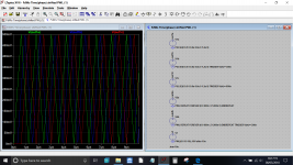
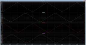
This one is slightly better, it makes it easy to set different delays (selected are 300ns and 600ns) (the maximum in this sample is 10sec).
There is something odd, the 300ns(blue) delayed version is smaller than the 0s(green) delayed and the 600ns(red) delayed versions, IMHO this is a bug/problem in LTspice (correct me if I am wrong). The anomaly is the same for PULSE- and PWL-voltage sources, also note that the 300ns version is distorted.
Attachments
Last edited:
I have try it, get from 0 to 500 mV needs plus and minus 1 volts, did change but get strange results, Need four 90 degree triangles of the same magnitude. <snip>
Demonstrate your voltage-source in a .asc-file and post here (do not add any other components in the file other than the one's needed to demonstrate your problem).
Last edited:
Thanks Mooly 🙂
This one is slightly better, it makes it easy to set different delays (selected are 300ns and 600ns) (the maximum in this sample is 10sec).
There is something odd, the 300ns(blue) delayed version is smaller than the 0s(green) delayed and the 600ns(red) delayed versions, IMHO this is a bug/problem in LTspice (correct me if I am wrong). The anomaly is the same for PULSE- and PWL-voltage sources, also note that the 300ns version is distorted.
Thanks fDW I see this one is the good one, I can sent the file to mike if you want if there is a bug, because it is strange that different level.
I have now used flip flops, but with yours I can sim much faster.
thank you.
...You could send the file to Mike, and I'm sure you would get a response as I've always found him really helpful.
Not now, I'm preparing for Munchen and that takes all priorities and I will have no objection to anyone sending it now, I will, if needed, look at it by the middle of next week.
Hi all
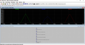
I have now 4 triangles and have lowering the frequency to plusminus 400 Khz .
What I see is that the triangles do not look good, except the first one and that she have different levels.
A bug? then I can send it to mike for advice, maybe implement a faseshift in voltage sources is a idea.
regards
I have now 4 triangles and have lowering the frequency to plusminus 400 Khz .
What I see is that the triangles do not look good, except the first one and that she have different levels.
A bug? then I can send it to mike for advice, maybe implement a faseshift in voltage sources is a idea.
regards
Attachments

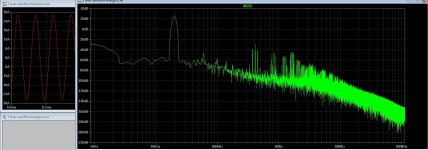
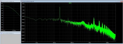
I have seen that in the multilevel simulation of the D amp things as supression of carrier is bad. pic two is much better with integrators and flipflops.
I send the file, if someone not already did.
regards
I send the file, if someone not already did.
regards
Attachments
Yes, to me, it's a bug.
The run-time dependency makes it even more like a bug.
And, to Kees52 [at all], it is a voltage source (PULSE and PWL)
And, the SINE-voltage-source has a phase property.
Please report, I will not have time to follow this op in the next 10 day's.
The run-time dependency makes it even more like a bug.
And, to Kees52 [at all], it is a voltage source (PULSE and PWL)
And, the SINE-voltage-source has a phase property.
Please report, I will not have time to follow this op in the next 10 day's.

If you isolate which specific functions cause the bug and package it up into a neat demo schematic, Mike is usually sure to respond and either tell you what you did wrong or fix the bug.
Also use plotwinsize=0 to rule out compression in the waveform viewer.
BTW, one of the things I had to deal with when making my saw/triangle source was that you have to account for risetime in the period/on time, otherwise one side will be longer than the other or you will get flat tops, or tops that are not the right voltage.
EDIT:
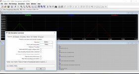
Okay, I've looked at the file. Guys, use a maximum timestep of 10nS at least, LTSpice is defaulting to a low timestep because you didn't specify that you wanted high time resolution. Don't go reporting this to Mike just yet.
BTW, one of the things I had to deal with when making my saw/triangle source was that you have to account for risetime in the period/on time, otherwise one side will be longer than the other or you will get flat tops, or tops that are not the right voltage.
EDIT:
Okay, I've looked at the file. Guys, use a maximum timestep of 10nS at least, LTSpice is defaulting to a low timestep because you didn't specify that you wanted high time resolution. Don't go reporting this to Mike just yet.
Last edited:
Okay, I've looked at the file. Guys, use a maximum timestep of 10nS at least, LTSpice is defaulting to a low timestep because you didn't specify that you wanted high time resolution.
Beat me to it, I could see it was a plotting resolution problem right away. LTSpice defaults are not going to give you good results.
I always use .OPTIONS numdgt=7, .OPTIONS plotwinsize=0, and the smallest timestep I can get away with.
- Home
- Design & Build
- Software Tools
- Installing and using LTspice IV (now including LTXVII), From beginner to advanced