Thanks Mooly - I think I'm clear on that after your explanation. I'd been assuming that because Spice automatically considers only the peak voltage (rather than pk-pk) when calculating RMS value(which it got right), then it would also do that when calculating average value. Is there a reason it doesn't do this?
Would you be able to let me have a copy of your 303 .asc file to experiment with?
Thanks
Mike
Would you be able to let me have a copy of your 303 .asc file to experiment with?
Thanks
Mike
Last edited:
Of course, here is the 303 and the 405. You will need to delete the .op for my model locations although the 303 used default models.
I guess LT just follows some form of convention and I wouldn't like to say where it originates. One of those that once you accept you never give a second thought to.
The big LT book (the LTIV Simulator) by Gilles Brocard also mentions the average function.
I found this:
Average Voltage of a Sinusoidal AC Waveform
Attachments

Thanks again Mooly - very useful link, which I have bookmarked. Thinking more, I suppose the averaging system in Spice is to allow for the complex (non-symmetrical) waveform for which the "0.637" function is not appropriate, but then you always have the option of selecting the part of the waveform you want averaging. As long as you understand what's going on - which I now do, so thanks!
Hope you won't mind me asking another (possibly related) question. I am doing power dissipation thinking re thermal design. My 303 sim. gives me a 0-50W sine wave at the load (presumably a plot of instantaneous value). Taking an average by same Spice method, I get ~26W. Which of these is the figure I should be using as the starting point for thermal calculations? What does the 26W average given by Spice mean in this case?
Or, perhaps neither of these is appropriate for my purposes.
Many thanks again for your help - AC theory is a minefield for the mathematically-challenged.
Last edited:
I can't even get 50 wrms/8ohm from my sim, at least not unless I increase the supply a few volts.
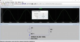
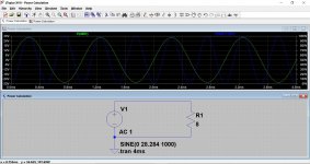
Here is a voltage source set for 28.284 volts peak which is the same as 20vrms which would give 50 wrms dissipation in the load.
If we now hover over the resistor and click 'ALT' and left click we get a trace of what LT call 'instantaneous power dissipation' which is amps times volts in the part concerned.
The peak voltage is 28.284 volts which gives a peak current of 28.284/8 which is 3.5355A
Multiplying those out gives a power of (3.5355*3.5355)*8 which is 100 watts.
So LT is correct and the instantaneous power at our chosen sampling point of the peak voltage works out.
The 'RMS' power is 50 wrms based on the rms voltage and load impedance.
Attachments
Mooly - revisiting the Quad 303 -issue - thanks for your patient explanations of power measurements in LTSpice, and for the copy of your sim. file for the 303. The latter was very useful for comparing with my own sim. I had to readjust the the output stage quiescent bias (showing about 60mA), and the output stage mid-point voltage, and then got the expected 50W average output on a 0.5V input sine wave. All the DC readings on my sim. were pretty much the same as yours, so I tried changing the transistor models - all made no difference. Looking for differences between my sim. and yours I could seen none apart from the biasing arrangement and the fact that you hadn’t included the over-current protection diodes (which aren’t important for simulation). On a hunch, I tried disconnecting the diodes in my sim, and eureka - everything became the same as yours, with output up from 30W to 50W, and all signs of clipping gone. I then tried adding the diodes in your sim. - and got exactly the symptoms that my original had had. So that seems to be the answer. My problem now is why is this happening? Only options seem to be 1) there’s something special about the diodes needed that an IN 4148 doesn’t match; 2) it’s an artefact of LTSpice, and it isn’t handling it properly; 3) it’s inherent to the protection circuit, but no one has ever noticed it before (pretty unlikely); 4) it is yet another thing that I’ve not understood. Can you throw any light?
Mike
Mike
I suspect the answer will be that the original old semiconductors used a different doping process to modern day parts and that results in small but significant differences in such parameters as forward turn on voltage... the voltage needed across B-E for a transistor to begin to draw base current, and similarly differences in the forward volt drop of the diodes.
The whole design depends 100% on those specific values for its operation. In simulation you could alter the 0.3 ohm resistors to allow less voltage to be developed across them in relation to the current.
The whole design depends 100% on those specific values for its operation. In simulation you could alter the 0.3 ohm resistors to allow less voltage to be developed across them in relation to the current.
Thanks to jazbo I got it working again. The triode-w1_dd.asy file was in the sym\misc file, it doesn't work there. I moved it to the sym file itself and it works fine. I'mvery sorry to try your patience. And thanks cogsncogs as well.
Mooly - Thanks. I've just tried those different models - only a little bit better than before on my sim - about 68W peak (with clipping) = 40W average. Power waveform seems to be clipping at that point. In all the stuff online on the 303, I've never seen this mentioned as a "real life" problem, so I wonder if it's something to do with Spice or its models. Mind you, anyone simming the circuit might not bother to put in the protection components. If you've still got the sim that just gave you 50W could you copy it to me?
Thanks for all your help.
Mike
Thanks for all your help.
Mike
Last edited:
Sorry ,my mistake - I've been working into 4ohms. Into 8 ohms the output is still only 26W.
Attachments
Last edited:
This tetrode library file contains a few models that have problems. They are there as I have been tinkering/testing them (mostly models from Steve Bench) and I haven't took the time to edit these out.Are there triode-w1_dd.asy corollaries for pentode and tetrode tubes?
If you place the tetrode_dd.txt file somewhere else other than the default LTspice install lib\sub directory, edit the SYMATTR ModelFile line (line 33) in the tetrode_dd.asy file to put the full path to the tetrode_dd.txt file.
Attachments
Temperature? The IS920s are not on the heatsink and are not dissipating at all in normal operation. Generally LTSpice is assuming all semiconductors are at the same temperature, far from true in this case, so Vf will be much higher than Vbe. This will raise the output power limitMooly - Thanks. I've just tried those different models - only a little bit better than before on my sim - about 68W peak (with clipping) = 40W average. Power waveform seems to be clipping at that point. In all the stuff online on the 303, I've never seen this mentioned as a "real life" problem, so I wonder if it's something to do with Spice or its models....
Mike
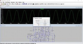
Good point David. I don't know just how much power can be squeezed from an original 303 into 8 ohms. The sim is in the right ball park though and I can achieve around 18.75 vrms/8 ohm with the default 2N3055 model and super careful tweaking of the midpoint voltage.
Look at Q6 2N5550 in the upper triple. Vbe =710mV at Ic=2mA seems very high to me, its far more than the datasheet typical VBE(SAT)Good point David. I don't know just how much power can be squeezed from an original 303 into 8 ohms. The sim is in the right ball park though and I can achieve around 18.75 vrms/8 ohm with the default 2N3055 model and super careful tweaking of the midpoint voltage.
I just tried Bob C's 2N5551 model for Q6 and Vbe came in at over 800mv, even with reducing the bias a little.
It is true that modern real parts do differ from the old due to doping process differences, and we see that a lot on the forum where an old amp gets rebuilt with modern parts and then find for example the bias current wont adjust.
It is true that modern real parts do differ from the old due to doping process differences, and we see that a lot on the forum where an old amp gets rebuilt with modern parts and then find for example the bias current wont adjust.
Mooly - your quiescent bias seems to be set very high - 125mA in Q8 collector (Quad say about 10mA).
Mike
Mike
800mV is way too high for any BJT where base current and Ic is low enough to avoid extra voltage due to the base spreading resistance
Quiescent current ended up high because it seems to interact massively with the midpoint adjustment which I was tweaking.
If you set R104 to 24.2k and the bias to 5k then I get symmetrical clipping and around 10.3ma current. Maximum unclipped out is now 17.2vrms for 0.59 volts input. Vbe now 0.675 volts on Q6. That is with the original default models.
This is a design that appears to depend considerably on the actual characteristics of the devices used.
- Home
- Design & Build
- Software Tools
- Installing and using LTspice IV (now including LTXVII), From beginner to advanced