Hi i am passing to opamps and i can see that the AD811 seems really great Spectacular THD+ noise indeed ... and all in just one piece almost 😳
But in the Analog Device catalogue there are so many other excellent products that do not show up in the LTSpice list
I understand that models are available in the AD website and actually i found one for the AD844 as .cir file
Is there a way to make it show up in the opamps list window so that i can pick it up ? 🙄
If there is somewhere a tutorial for this i missed it
I haven't done this since I put this thread together.
Post #146
https://www.diyaudio.com/community/...from-beginner-to-advanced.260627/post-4067126
How easy it would be I don't know. The .cir file would need altering I think (the pin allocations) and there is also a 6th pin needed for compensation.
If you open the .cir file using notepad you will see the pin allocations which seem a bit odd tbh in the numbering.

Good evening and thank you very much for your always precious Help I think i will stick with the default opamps
Unfortunately some older but very popular ones are missing like the ad797 but also other i have seen used widely
Anyway the ad811 already looks really great and the THD graph looks great I know of at least one brand using it in one of their best preamps
Unfortunately some older but very popular ones are missing like the ad797 but also other i have seen used widely
Anyway the ad811 already looks really great and the THD graph looks great I know of at least one brand using it in one of their best preamps
Attachments
The way many basic models work in LTspice doesn't always accurately reflect the real world performance for things like distortion and also things like input bias current and input offsets.
The AD811 is a CFB or Current Feedback type opamp which is fundamentally different to the more usual Voltage Feedback type we use in audio. This one is optimised for low impedance high frequency work such as video rather than audio.
For example if you run your simulation using an LT1001A which is really a bit like a 741 then the results for distortion are excellent. There is also no detectable (only femto volt) offset voltages.

Now lets drop a 'real' 741 into the simulation. The distortion is more accuratly modelled and now there are very high DC offset voltages in the 160mv region which is as it should be. The 741 used here is based on the model included in LTspice in the 'Educational Folder'

This is the 741 model used.

The AD811 is a CFB or Current Feedback type opamp which is fundamentally different to the more usual Voltage Feedback type we use in audio. This one is optimised for low impedance high frequency work such as video rather than audio.
For example if you run your simulation using an LT1001A which is really a bit like a 741 then the results for distortion are excellent. There is also no detectable (only femto volt) offset voltages.
Now lets drop a 'real' 741 into the simulation. The distortion is more accuratly modelled and now there are very high DC offset voltages in the 160mv region which is as it should be. The 741 used here is based on the model included in LTspice in the 'Educational Folder'
This is the 741 model used.
Good evening ! do you mean that the FFT i get for the ad811 is not accurate ? that is unfortunate because it is immaculate
Regarding its use in audio i know of at least one brand using it Jeff Rowland in the Synergy preamp https://www.stereophile.com/solidpreamps/646/index.html
Do you think that the circuits suggested in the datasheets are tested and surely working ? that would be a great help for anyone who wants to try one application
Regarding its use in audio i know of at least one brand using it Jeff Rowland in the Synergy preamp https://www.stereophile.com/solidpreamps/646/index.html
after reading this review i purchased a pair but i cannot find them again I had a good selection of opampsThe Synergy features Jensen 10-KB-D input-coupling transformers, Analog Devices AD-811 audio op-amps, and a Crystal Semiconductor CS-3310 digital attenuator...
Do you think that the circuits suggested in the datasheets are tested and surely working ? that would be a great help for anyone who wants to try one application
Attachments
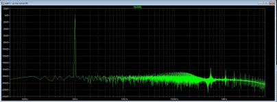
do you mean that the FFT i get for the ad811 is not accurate ? that is unfortunate because it is immaculate
What is modelled differs from device to device. It all comes down to how comprehensive the model is. The FFT shows essentially zero distortion and no opamp is that good. Look at the db scale at the left, 170db down isn't even measurable by normal real test equipment.
Its a good opamp for sure but its strengths lie in its intended use which is handling video rather than audio.
I've also noticed your timestep is entered as '100' as well you having a .options command entered. Set differently. Nothing is that good 😉
Good morning and thanks a lot again I understand that i do not understand the theory behing settings
Anyway i have similar result with the LT1122 i guess a more audio oriented device
I did not know that Analog Devices and Linear Technology merged together There are so many LT opamps in the library I am more than sure that many should works exceptionally well for a line bruffer or preamp
As I am using sources that output usually around 2Vrms i am focusing just buffers without gain
I have always in mind that there is no gain without pain 🙂
May i ask which would be your buffer of choice ?
Thanks a lot again
May i ask which would be your buffer of choice ?
I honestly like the old TL071/2/4 series of opamps and used correctly they can sound really good. FET input mean no offset worries or AC coupling needed to block any offset, not that AC coupling is automatically a bad thing.
For simulating the LT1056A opamp is very similar to the TL071.
As I am using sources that output usually around 2Vrms i am focusing just buffers without gain
You need gain 🙂 If you have a voltage gain of zero you will always get zero signal at the output 😉 You want a gain of 1 or unity gain.
Also remember that the voltage you set in simulation is a peak voltage so your 2 volts is only 1.4 volts rms. You need to enter 2.83 to get 2 volts rms. You should also design for worst case situations so design for higher levels than that and make sure it can drive the load impedance you want to drive.
Other real world opamps to use are the LM4562 and the OPA134/2134/4134 series. Those are all recognised audio oriented opamps and are easy to use. A lot of the really fast designs need extreme care in layout and implementation and many are only available in very small surface mount type outlines.
Hi thanks again indeed And yes of course I meant unity gain I like the idea of having a great attenuator with a buffer before facing the power amp issue Source will be some digital I still have doubts about the best settings when sim opamps ... but my rationale is that using same settings the best circuit will have the best graph anyway Maybe the real will be worse but i will look at the difference between one and another
I think i have a great basis of advice to work on Let's sim ! 🙂👍
I think i have a great basis of advice to work on Let's sim ! 🙂👍
Hi thank you so much for kindly sharing you excellent work with us Very kind of you indeed
I will read it carefully hoping to understand something For now i have just use as a basic file one kindly provided to me by Mr Mooly
it seems to work quite good for circuits made out of discrete parts
I must say that i am a beginner without much more curiosity than real knowledge
But there are trivial common rules that applies to almost anything
One is that if i get results that are not realistic or the tool i am using is not right or i am using it wrongly
If you look at the fft above you will understand what i mean
I am more optimistic for simulating discrete designs
But to get very good performance from discrete designs is very very challenging I am simulating commercial units of which i got the service manuals or the schematic Just for an example i could not simulate a quite simple Naim line stage I cannot get the FFT ...
I have the feeling that many schematic product of reverse engineering are not completely reliable
Anyway i will try again
For the next month i will continue to sim commercial units and see if how the results will compare with the declare specifications
I am quite fascinated by this topic I have a schematic of a discrete opamp with about 52 parts active and passive It will be a good training for using the SW commands
Have you looked at the Educational simulations included with LTspice? There are all sorts in there, amps, oscillators and other interesting stuff 🙂
They are located in the 'Examples' folder. There is a discrete 741 opamp in there as well. Where that folder is located depends on your installation and how you set it up initially and also whether you are using the latest LT24 or the older LTXVII version.
They are located in the 'Examples' folder. There is a discrete 741 opamp in there as well. Where that folder is located depends on your installation and how you set it up initially and also whether you are using the latest LT24 or the older LTXVII version.
hi thank you i will do I have downloaded the latest LT24 two weeks ago But maybe i am too optimistic but the results are fine with discrete with your excellent settings I have understood that models for opamps are debatable In case i will look at the circuits proposed in the datasheets
To be precise many years ago i made a little line preamp with two ad797 using the parts showed in the opamp datasheets
I had noise when rotating the volume knob from zero up and i dismissed the idea Later i realized that a small 100 ohm resistor placed at the wiper out could have solved the issue Silly me I hope to find again the opamps in some closet I bought other models too
The idea is using as a testing pcb one of those sold for kit for the NE5534 op amps And use the removable sockets hoping that they will not contribute to noise I will look at the discrete 741 opamp you mention
I have already sim some discrete opamps The problem is that the i do not have the models of the bjts actually used in the commercial units
So i had to use what i can find in the default library No problem The result are pretty decent
What i do not like is the dissipation is not symmetric Complementary NPN and PNP are quite different in dissipation
Have you actually found this folder?

For LT24 it could be in one of two places depended what option you used to install it.
https://www.diyaudio.com/community/...from-beginner-to-advanced.260627/post-7665885
If you want to design a simple buffer we can do that in on here in LTspice and try and make it 'universal' to suit a lot of common dual opamps and then you can try a few and listen for yourself 🙂
Hi yes ! i found the folder attached and i have started looking at it
i think that it is too early for design something I need to read something first
I understand your point about the sim of opamps I thought that it were easier to sim a single opamp than a complex discrete opamp
I have tried to sim a schematic found on line of the Bryston doa 33 discrete opamp and even if i have used different bjts the result is quite nice
I have no clue if that design is stable also when wired to get unity gain .... how can i chek stability ?
I am sure that with the actual bjt models the results should have more accurate
anyway for an ignorant like me the program is very useful because i can check how the HD changes changing Ibias Vsupply etc.
And of course the sw tells when something is very wrong with the circuit
So end my ramblings i am still in the learning phase It will take me about one month more or less
I am so amibitious that i have not dismissed the idea of a discrete buffer even if it seems more and more a hopeless dream
It looks so difficult to achieve the same performance of a decent opamp with a discrete design
For instance i would be curious to know if the discrete equivalent of the 741
https://www.diyaudio.com/community/attachments/screenshot-2024-05-23-195248-png.1313607/
performs at the same level of the monolithyc opamp
The discrete equivalent for sure is very challenging to build but offers a lot more choice like higher voltage supplies
It is astonishing to know how many semiconductors are packed is such tiny parts Unbelievable
Thank you very much again and have a nice day
gino
Attachments

I was simulating in LTspice old version, and find a problem there, I do not now it is still present
in the new one.
Do somebody now where to give info to the writer of this program? maybe these people can do something with it,
the fact I see problems is because I do sim a lot, yes aaaaa lot.
Movie let see it loops in the fft, I can not stop it anymore and needs to hardstop it in windows itselfs.
I have find out that the distortion measures what is a little confusing with partial and total distortions, that the partial
distortion is the .four setting and total is all together, so the switching stage do als get into account, how deeper the
supression of the carrier in class d how lower total distortions. little confusing because I do not need the carrier measured
so maybe include a noise measurement included in this is of valeu.
regards
For instance i would be curious to know if the discrete equivalent of the 741
https://www.diyaudio.com/community/attachments/screenshot-2024-05-23-195248-png.1313607/
performs at the same level of the monolithyc opamp
Yes it is pretty good and close to a real 741. That example is in that folder and is ready to run.
I would recommend you open and resave any you are interested in to another location and that way you preserve the originals.
It can show as obvious oscillation on the signal when you run the sim and you can also look at phase margins to see it it seems stable.I have no clue if that design is stable also when wired to get unity gain .... how can i chek stability ?
Transistor models have much less effect than you might think when putting audio circuits together (which in scheme of things are all very low frequency).I have tried to sim a schematic found on line of the Bryston doa 33 discrete opamp and even if i have used different bjts the result is quite nice
I still think you should try and build a real design with some common opamps and listen to it 🙂 You would learn so much doing that. Something like a simple two stage design using an opamp to give a gain of say 5 or 10 along with an attenuator to bring it back to the same level and follow that with a buffer. Use 741's or their dual equivalent like the 1458 and give them a listen and then swap them for something much better like an lm4562 or an OPA type FET opamp and listen again. Is the 741 really that bad? Prove it for yourself.
You need to a post a sim that you have issues with making sure that it will "Click and Run" for anybody (all models included etc etc) and then we can see if we have the same error or not.Do somebody now where to give info to the writer of this program? maybe these people can do something with it,
Thank you so much again 🙂👍 if i run it right to be honest it does not look that clean .... i mean the spectrumYes it is pretty good and close to a real 741. That example is in that folder and is ready to run.
I would recommend you open and resave any you are interested in to another location and that way you preserve the originals.
It can show as obvious oscillation on the signal when you run the sim and you can also look at phase margins to see it it seems stable.
Transistor models have much less effect than you might think when putting audio circuits together (which in scheme of things are all very low frequency).
Anyway if i understand well they design a discrete circuit and then they make the opamp scaling down the size ? i mean all start with a normal circuit ?
So in order to get really great performances the part count cannot be low (in the face of minimalists...)
i see I do not want to sound lazy but the first stage is really needed ? is it not enough a 10Klog pot followed by the buffer ? as a start at leastI still think you should try and build a real design with some common opamps and listen to it 🙂 You would learn so much doing that. Something like a simple two stage design using an opamp to give a gain of say 5 or 10 along with an attenuator to bring it back to the same level and follow that with a buffer. Use 741's or their dual equivalent like the 1458 and give them a listen and then swap them for something much better like an lm4562 or an OPA type FET opamp and listen again. Is the 741 really that bad? Prove it for yourself.
I guess the best bet could be to use as reference a circuit contained in the datasheet of the relevant opamp ?
those should be surely working and tested
Again the LM741 thd spectrum below does not look that great Simple discrete circuits look quite better ... often the 2nd harmonic is lower than - 100dB 🙄
Attachments
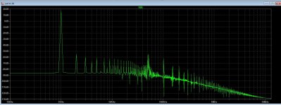
Welcome to the 741... and this is why you should have a listen to one. Make your own mind up and see what it is really like to listen to.Again the LM741 thd spectrum below does not look that great Simple discrete circuits look quite better ... often the 2nd harmonic is lower than - 100dB
Having looked at the model run I notice there is zero bias current in the output stage which is bit odd and so I've altered R9 to give 1ma bias which would be about right I think.
I've set the sim to run longer and also set the timestep and reduced the input signal to more realistic audio levels. Now it looks a bit to good 😉
Attachments
- Home
- Design & Build
- Software Tools
- Installing and using LTspice IV (now including LTXVII), From beginner to advanced