Does this "discovery" affect the way you suggested we organise our files?
I am lost when trying to save and retrieve LT files.
There are some that I can never find, I don't know where LT saves them.
Search in Win7 does not work like it did in very old Win versions.
I am lost when trying to save and retrieve LT files.
There are some that I can never find, I don't know where LT saves them.
Search in Win7 does not work like it did in very old Win versions.
You have to be very careful with LT on where you save files (in order to keep track of things) its so so easy to click save and find its stored your file in the dedicated LT program files. Its absolutely up to you to select the folder you want it saving in because normally LT defaults to the Program Files which are really in a protected area of the operating system.
There is no easy way to find rogue files but it is definitely worth a quick trawl of the program files (c:\program files x86 and look in LTC folder) where any added by you should be easy to identify because of the 'date changed' marker or just by you recognising a file name.
Its also well worth searching for .raw and .net files which could get left behind if you for example change a file name and save it. LT won't then automatically delete the .raw and .net files from the previous file name association.
Hello Mooly. The difficulty I had is resolved. I readily opened the attachments in my post [and in posts of other threads] which displayed their schematics in a dedicated LT window. I'll enable your suggestions on the PC
Hello AndrewT. Mooly emphasized early in this thread to park the generated new schematic files in one's personal space instead of LTs. Todate, I am able to find each and every one, and further delete .raw, .net .wmt files which I consider spent; unless they have some hidden value!
Best regards to both of you.
I opened one .asc file with notepad, it's only 2 lines!!! Is it that short?If you open that with notepad, you will see it's actually english code. LTSpice reads that code to draw a schematic. LTSpice uses it's own code so only it can convert the file to an image. In LTSpice there is an option in the Tools menu to save the current work window as an image. Make sure you have the schematic window selected when you do this. Then you can upload the resulting image.
If that doesn't work for some reason you can take a screenshot and post that.
Also, I gone into tools and I don't know how to save as image. I always want to know how to copy the schematic from LTSpice into JPEG image. Can you elaborate a little?
Thanks
Hi Mooly
I have a few quesitons
1) Do you know how to do noise simulation for opamps? I have a project that I need to design a very low noise opamp circuit ( to be specific, transimpedance amp circuit). Can LTSpice simulate noise using different opamps and different value resistors?
2) I learn from your instruction and actually import the model files of opamps from Analog Devices, copy into notepad and ran the simulations. But how do I know LTSpice is reading the model correctly? I looked inside the files, it looks different. But the LTSpice never complain. Attached is the .txt file I copied from Analog Devices. Do you know what is the meaning of the terms?
3) When I do frequency sweep to look at the gain and phase, in the simulation graph, the left side is dB in gain from input to output. How do I read the phase on the left side? I notice for an inverting opamp, the phase starts at 180deg and then go go down towards zero or even negative. Does that means because it's an inverting amp, the phase starts at 180deg( out of phase), then as phase lag comes in and the angle decrease from 180 to 150 to 90 ....to 0. Then even go to -ve phase angle due to phase lag?
4) I know if I put the mouse pointer to the gain graph, I can read the gain, the frequency and the phase of that point. But when I point to the phase graph(dashed line), what is that read?
Thanks
Attachments
Last edited:
I opened one .asc file with notepad, it's only 2 lines!!! Is it that short?
Also, I gone into tools and I don't know how to save as image. I always want to know how to copy the schematic from LTSpice into JPEG image. Can you elaborate a little?
Thanks
Someone with Windows should post a screenshot showing the option. I'm using Linux and the option doesn't show up in the menu.
Many ways. In the Tools menu the first option is Copy bitmap to Clipboard - select that, and then in any painting or image editing program, like Windows Paint, just do a Paste. Should see the image, and then save as JPEG, etc.Also, I gone into tools and I don't know how to save as image. I always want to know how to copy the schematic from LTSpice into JPEG image. Can you elaborate a little?
Eagle and LTspice native OSX on my Mac.
I've recently decided to do some audio amp design at home, using my old, trusty Mac. Will get a PC for the purpose later, but for now, it's my 7 year old iMac.
I found Eagle and LTspice native on the Mac, for free from their respective websites. I found a file called spice.ulp from the Eagle website that lets Eagle export a spice netlist. I edited spice.ulp, because it spits out a bunch of junk comment lines, which made the netlist harder to read. Fixed. Turns out the .ulp scripting language is pretty standard codespeak.
Schematic capture in LTspice works OK, but I can't make a PCB from an LTspice schematic, so Eagle is used. Also, it's ironic that LTspice for Mac has a reduced gui, and works using keyboard shortcuts.
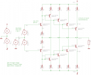
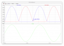
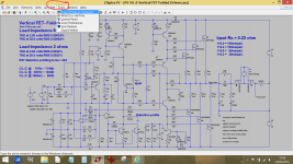
So far, so good, and relatively easy. I thought I'd start by simulating an output power stage for a 200+ W amp. Here's the schematic, the netlist, and a transient simulation:
I've recently decided to do some audio amp design at home, using my old, trusty Mac. Will get a PC for the purpose later, but for now, it's my 7 year old iMac.
I found Eagle and LTspice native on the Mac, for free from their respective websites. I found a file called spice.ulp from the Eagle website that lets Eagle export a spice netlist. I edited spice.ulp, because it spits out a bunch of junk comment lines, which made the netlist harder to read. Fixed. Turns out the .ulp scripting language is pretty standard codespeak.
Schematic capture in LTspice works OK, but I can't make a PCB from an LTspice schematic, so Eagle is used. Also, it's ironic that LTspice for Mac has a reduced gui, and works using keyboard shortcuts.
So far, so good, and relatively easy. I thought I'd start by simulating an output power stage for a 200+ W amp. Here's the schematic, the netlist, and a transient simulation:
Attachments
Thanks, you make my day. It's so easy.Many ways. In the Tools menu the first option is Copy bitmap to Clipboard - select that, and then in any painting or image editing program, like Windows Paint, just do a Paste. Should see the image, and then save as JPEG, etc.
Looking at noise simulations for opamps is something I have never tried before, however its a valid question and so this is the result of a quick test 🙂
And so a big disclaimer... as this is a first, I might well have made some huge basic error somewhere...
I took a basic non inverting opamp circuit configured for a gain of 101. The feedback components were 1meg and 10k, deliberately high values to see what kind of results we get. These values would be hopeless for a real audio circuit and so I've set the simulation to look at the noise over just the 20Hz to 1kHz range.
Alan asks whether the models used reflect reality for noise and the answer is that I have absolutely no idea. This leads me on to using two very different devices for this test. The first is taken direct from the LT examples included with the basic installation of LT and is the good old 741 opamp. If anything is going to be noisy then this is it. The second is the LT1056A which is a modern FET device.
Lets see how they get on.
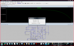
We use the <Noise> tab on the <Edit simulation> option as seen here.

The 741 comes out at 2.2uv/√Hz when looking at the output. LT lets us look at the 'total' RMS value over the frequency range of interest and that is shown as 70uV. The opamp runs on -/+15 volts rails and so might be expected to swing around -/+12 volts at the output. 12 volts peak is 8.4 volts RMS. To see the RMS value just press and hold CTRL while clicking the trace designation a the top of the graph.

Taking these two figures we can then calculate using 20log (V1/V2) that there is a 101 db ratio or signal to noise ratio (which come out the same as the gain... coincidence).
Lets try the LT1056A FET device.
This has a noise contribution that falls with frequency but looking at the scale and the result is not as dramatic as it first appears.

In fact the RMS value for the noise over the same bandwidth is 64uv. So calculating that out and we get 102 db.
Both those results look hopelessly optimistic to me... if you had asked me the question on noise then I would probably have guestimated the 741 at somewhere in the 65 db region, the FET a little better given the impedances involved.
Hmmm.... lets bring the circuit impedance down by using 10k and 100 ohm resistors and see what happens. Now the FET opamp comes in at 104db and the 741 at 103 db. The 741 also has a DC offset that varied between the different feedback values of just 34 millivolts and 134 millivolts. I would have thought it would be worse than that (if you had just asked me the question based on values used)
The FET device over a 200kHz bandwidth clocked 86db and the 741 89 db.
And so a big disclaimer... as this is a first, I might well have made some huge basic error somewhere...
I took a basic non inverting opamp circuit configured for a gain of 101. The feedback components were 1meg and 10k, deliberately high values to see what kind of results we get. These values would be hopeless for a real audio circuit and so I've set the simulation to look at the noise over just the 20Hz to 1kHz range.
Alan asks whether the models used reflect reality for noise and the answer is that I have absolutely no idea. This leads me on to using two very different devices for this test. The first is taken direct from the LT examples included with the basic installation of LT and is the good old 741 opamp. If anything is going to be noisy then this is it. The second is the LT1056A which is a modern FET device.
Lets see how they get on.
We use the <Noise> tab on the <Edit simulation> option as seen here.
The 741 comes out at 2.2uv/√Hz when looking at the output. LT lets us look at the 'total' RMS value over the frequency range of interest and that is shown as 70uV. The opamp runs on -/+15 volts rails and so might be expected to swing around -/+12 volts at the output. 12 volts peak is 8.4 volts RMS. To see the RMS value just press and hold CTRL while clicking the trace designation a the top of the graph.
Taking these two figures we can then calculate using 20log (V1/V2) that there is a 101 db ratio or signal to noise ratio (which come out the same as the gain... coincidence).
Lets try the LT1056A FET device.
This has a noise contribution that falls with frequency but looking at the scale and the result is not as dramatic as it first appears.
In fact the RMS value for the noise over the same bandwidth is 64uv. So calculating that out and we get 102 db.
Both those results look hopelessly optimistic to me... if you had asked me the question on noise then I would probably have guestimated the 741 at somewhere in the 65 db region, the FET a little better given the impedances involved.
Hmmm.... lets bring the circuit impedance down by using 10k and 100 ohm resistors and see what happens. Now the FET opamp comes in at 104db and the 741 at 103 db. The 741 also has a DC offset that varied between the different feedback values of just 34 millivolts and 134 millivolts. I would have thought it would be worse than that (if you had just asked me the question based on values used)
The FET device over a 200kHz bandwidth clocked 86db and the 741 89 db.
Attachments
Hello Alan0354. Pardon my simple question. Where is and how do I reach the clipboard? Thanks.Thanks, you make my day. It's so easy.
N.B. The sequence of keystrokes you used is the method which made your day. I hope that you could share it. Best regards.
Last edited:
Hello Alan0354. Pardon my simple question. Where is and how do I reach the clipboard? Thanks.
N.B. The sequence of keystrokes you used is the method which made your day. I hope that you could share it. Best regards.
I think it was Frank actually that mentioned this one.
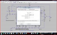
Like this 🙂 You can then paste it direct into some suitable program such as Paint or Wordpad.
Attachments
Thank you fas42. My apology for omitting my thanks [to you] for your valuable suggestion. Thank you Alan0354 for asking the question which triggered the valuable response by fas42. Thank you Mooly for your ongoing support and help. I am close to target which I'll show as proof in a future post. I have never opened "clipboard" in windows word till today.
Best regards.
Best regards.

I don't know whether that would help you. I went on "Tools", copy the bitmap file. Then I just open a new file in photoshop and paste!!! It worked like a champ. I bet if you find any software that can generate JPEG file, paste onto it and it should work.Hello Alan0354. Pardon my simple question. Where is and how do I reach the clipboard? Thanks.
N.B. The sequence of keystrokes you used is the method which made your day. I hope that you could share it. Best regards.
Hi Mooly
I just got back from dinner. I have to take my time to experiment with it. I'll get back to you later. Thanks for your time. So far, it's been very helpful reading your posts on this.
Thanks
Alan
I just got back from dinner. I have to take my time to experiment with it. I'll get back to you later. Thanks for your time. So far, it's been very helpful reading your posts on this.
Thanks
Alan
Right click -> paste
Whenever you "cut" or "copy" something, it goes to what is called the Clipboard. You can copy something from one folder or program, and it will stay on the clipboard so you can paste it into other programs. This has been standard computer behavior for decades.
Whenever you "cut" or "copy" something, it goes to what is called the Clipboard. You can copy something from one folder or program, and it will stay on the clipboard so you can paste it into other programs. This has been standard computer behavior for decades.
In my opinion it's just as easy to use the Windows "Snipping Tool" as the "Copy to Bitmap" feature. The Snipping Tool is more versatile - you can grab entire windows, portions of a window, two or more windows in one image, or an arbitrary (irregular shape) portion of the display. You can also save the image in *.png, *.jpg, *.gif, or *.html formats; or plunk it into a graphics editor like Paint for additional editing.. . . Then I just open a new file in photoshop and paste!!! It worked like a champ. I bet if you find any software that can generate JPEG file, paste onto it and it should work.
It's worth your time to learn this. Trust me. The Snipping Tool is really quite user-friendly and an improvement over previous tools for this task. I believe it shipped with some XP versions, most flavors of Vista, and everything since then. (The default Windows installation options didn't always give it an icon or listing in the "Start" menu. Once you find the program files it's easy to add "Snipping Tool" shortcuts to your desktop, "Start" menu, etc.)
Seed a search engine with " vista snipping tool " to learn more, or see:
"How to Take a Screenshot with the Snipping Tool on Microsoft Windows" at http://www.wikihow.com/Take-a-Screenshot-with-the-Snipping-Tool-on-Microsoft-Windows
"Snipping Tool" at http://en.wikipedia.org/wiki/Snipping_Tool
etc.
Examples of "Snipping Tool" captures are attached to my old posts at :
http://www.diyaudio.com/forums/soft...should-know-about-ltspice-19.html#post2719510
http://www.diyaudio.com/forums/equipment-tools/217973-can-any-digital-scopes-do-x-y.html#post3127792
http://www.diyaudio.com/forums/soft...mages-ltspice-circuits-plots.html#post2548002
Dale
- Home
- Design & Build
- Software Tools
- Installing and using LTspice IV (now including LTXVII), From beginner to advanced