And the plot. Which won't upload in .emf format. Try this. Which ain't pretty, but you get the idea. You can modify the values with log10 if you want to see what happens.
Attachments
Last edited:
Hello all guys.
Is there a way to simulate a potentiometer (not rheostat)?
How do I simulate a log pot?
Many thanks in advance.
I've attached a zipped folder with a selection of nine pots from the LTspice users group. Unzip the folder and open potentiometer_standard_test.asc. Click Run and it plots the response of the various types of pot.
Note that for all these pots the rotation is 0-1, not 0-100%. There are instructions for use on the schematic.
Attachments

See post https://www.diyaudio.com/forums/sof...ltxvii-beginner-advanced-280.html#post6675911
What was not clear here, and if so (not clear), why not ask questions about it.
What was not clear here, and if so (not clear), why not ask questions about it.
t
To whom (which post) is this addressed?
See post https://www.diyaudio.com/forums/sof...ltxvii-beginner-advanced-280.html#post6675911
What was not clear here, and if so (not clear), why not ask questions about it.
To whom (which post) is this addressed?
Anyone that shows interest 🙂
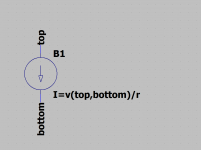
The point is, a resistor is depicted as (in the example given) r=u/i
This can be translated to a current source as i=u/r
The example given uses a current source (in the example attached B1)
The voltage across the current source is given by v(top,bottom)
The current then would be v(top,bottom)/r where r is the resistor to be simulated
The point is, what could be simpler, one component B1 and one formula i=v/r
The question remaining is, what is not clear (or, otherwise, why do we need more samples) in general it would be better to search understanding of the problem at hand, not try and try again with more and more samples.
Just trying to clear things up 🙂
Attachments
t
To whom (which post) is this addressed?
In general, posts are reactions to the directly preceding posts unless otherwise indicated, like when posting a (new) question. It is not, generally, common to quote the directly preceding posts, unless this is needed for absolute clarity.
Discussions/postings in forums are normally directed to 'the people' in general
I am perfectly aware that reactions to the preceding post do not normally quote from that post. It just seemed rather a strange reaction to my post, which is why I was not sure if it was intended as a reaction to my post or to another post.
Now, if I have understood correctly, you are therefore asking me, in post #2803, why I am not asking questions about your post #2794. Is this correct?
The implication would appear to be: why am I posting an .asc file with numerous potentiometers when you have already posted #2794. Is this correct?
I posted the folder because it contains numerous oven-ready potentiometers with a good symbol and excellent ease of use. There would appear to be a number of posters who have problems with potentiometers, and I posted the folder to help them, especially Osvald de Banfield in post #2791. Despite your post, posters continue to have problems, so hopefully my post will provide additional help to them. The potentiometers in my post were authored by the late Helmut Sennewald of the LTspice users group, incidentally.
I hope this clarifies things for you.
Way to personal, I just tried to answer the first part of the original question
https://www.diyaudio.com/forums/sof...ltxvii-beginner-advanced-280.html#post6675401
e.g. not the "How do I simulate a log pot?" calculus part
The models answer, partly, the calculus question(s) on how to translate (pseudo) an angle of rotation (like from a real-world potentiometer) into an value of resistance, be it linear, logarithmic, exponential or perpendicular (related to what-ever). These are different questions being answered.
The potentiometer questing was answered by using 2 simulated resistors, by way of an set of current sources, and a set of functions (where you can substitute any).
Any way, this is now about the difference between simulating and emulating, the potentiometer can be emulated by two resistors and then step commands can be used to emulate, when using simulation (like using the current source) no stepping is needed and a (pseudo) continues workflow may be used. It just depends on what is needed.
Last edited:
Hi All
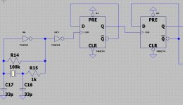
I get no signal from the flipflops, doe someone now why? I have only signal 5v top from the oscillator to input first FF but no output. Maybe the PRE or CLR pin?,.
thanks.
Have you tied the PRE and CLR to the wrong rail/logic level? The dot or circuit indicates that those signals are inverted or active low instead of the normal active high.
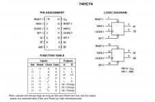
I suggest you try switching the PRE and CLR to the opposite logic level (high) and look at the linked datasheet and attached function diagram.
https://www.mouser.com/datasheet/2/308/74HC74-108792.pdf
Attachments
Guys mine thanks is byond limits.
I had first the simpel digital parts, so here it does not be important where to connect, was confusing.
Yes I had to read the datasheets, sorry for that.
regards
I had first the simpel digital parts, so here it does not be important where to connect, was confusing.
Yes I had to read the datasheets, sorry for that.
regards
Everything works (or doesn't work) the way you have drawn. You know that the circle on the input means that the active input level is "0". By connecting the setup and purge inputs to the common you are doing setup and purge at the same time, which prevents the triggers from working the way you want them to. Feed "1" to the ill-fated inputs. I don't know what parameters you have set in the logic elements, so I don't give the value in volts.
But even by making these changes your circuit will not work (or will not work at the right frequency). Normal logic elements do not work in quartz oscillators. You have to get a 74HCU04 which will work in the circuit!
But even by making these changes your circuit will not work (or will not work at the right frequency). Normal logic elements do not work in quartz oscillators. You have to get a 74HCU04 which will work in the circuit!
Oke thanks, I am not so experienced with logic, but you are right need to read more. the rfeason is I did use standard digital components before and not the lib versions, these are clr are grounded and work, so I was confused now.
Oh yes now I have a talk about logic, does somebody now where to find the CD4035A model, otherwise need to build one?
thanks huys.
regards
Oh yes now I have a talk about logic, does somebody now where to find the CD4035A model, otherwise need to build one?
thanks huys.
regards
Last edited:
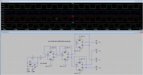
Oke, have done what you guys advise. It works now. But I have just one question left, the capacitors before the integrator opamp does charge, so before it is not a good triangle, can I set in LT spice something so the capacitor charged such that signal on opamp is right, I hope I explane right.
Thanks.
Thanks.
Attachments


I suggest to use the highest resistance shunting the xtal possible. The usual values are about 10M, but I have used up to 22M in my designs. In such a way, the reduced load in the xtal increases its stability, amplitude and reduce drifts. This is only possible with all CMOS gates. TTL gates are not suitable for such a high rasistance values.
- Home
- Design & Build
- Software Tools
- Installing and using LTspice IV (now including LTXVII), From beginner to advanced