Geez, it's been almost 2 months and I am just now getting to this! Lots of interference with family trauma, mother in and out of hospital, brother suddenly died (not surprising, life long 3 pack smoker with uncontrolled diabetes and mentally disabled, just unexpected), school starting for the little one, then the big one's firm shut down. Oh, and the wife's back to her teaching gig in Taiwan. Whew!
Anyhow, I have some questions now that I am getting serious about testing a bunch of circuits. Is the CMic a ceramic or film capacitor? I notice that RMic in 000 has R5.6k, 001 has R50k pot, and 002 has R1k switch. Why is that so? On the Single/Dual Power Supply circuits, C1 is 3.3uF, but 000-003 has it as 100pF. Why is that so?
I really appreciate all of this info, it is fascinating how these things work and vary. Thanks!
.
Well kiss mah grits, so it's true what they say about bad pennies. And wait, you live where, in Taiwan? Well good grief, no wonder you're confused, those people don't even speak English.
No wait, they do, don't they? Well, moving right along.
<< Is the CMic a ceramic or film capacitor? >>
Ceramic capacitors are generally frowned upon for audio, film capacitors are preferred. Mylar film is the most readily available, many insist on more exotic blends.
Note that this is talking about the audio circuit. Ceramics are commonly used in power supplies--although you can get into a fistfight about that too.
<< I notice that RMic in 000 has R5.6k, 001 has R50k pot, and 002 has R1k switch. Why is that so? On the Single/Dual Power Supply circuits, C1 is 3.3uF, but 000-003 has it as 100pF. Why is that so? >>
Wait...are you actually doing the math on these circuits? Don't! Again, these are representative, intended to illustrate whatever principle was being discussed at the time. They're not construction projects. They could be built, but niceties have been left out. Well, more specifically...
<< On the Single/Dual Power Supply circuits, C1 is 3.3uF, but 000-003 has it as 100pF. Why is that so? >>
This is apples and oranges. The two capacitors are both identified as C1, but they're in different circuits, so unless otherwise stated you can't relate them in any way.
A picofarad (pF) is a very, very small capacitance. Note that usually we work in microfarads (uF), 1uF = 1,000,000pF.
Picofarad capacitors usually come into play at supersonic and/or radio frequencies, and that's the case here. The 100pF capacitor shunts frequencies above 100kHz to ground. This protects against noise, protects against oscillation, and also unloads the NE5532 by not making it deal with frequencies that are not of interest anyway.
I probably shouldn't have put it in, but unlike your better half I don't have a lesson plan, things happen ad hoc.
The 3.3uF capacitor is part of a high pass filter for the audio circuit. "High" starting at around 20Hz. Also called a bass rolloff filter. Same idea of unloading the NE5532, also it removes low frequency noise such as turntable rumble. It also blocks DC. >>
<< RMic in 000 has R5.6k, 001 has R50k pot, and 002 has R1k switch. Why is that so?
You're talking about post #49, and again there are apples and oranges. Point A is the same point in all the circuits shown, but beyond that they're not the same circuit.
<< RMic in 000 has R5.6k >>
The value of Rmic was chosen after I looked at some Panasonic tech publications, but sorry, I have no memory of the specific reason--or the specific publication.
<< 001 has R50k pot >>
Ahem, its name is Pot1, and its value is 50k. That value was chosen as approximately equal to R1 so when Pot1 is at maximum resistance the input signal level is approximately cut in half. Arbitrary, actually.
<< and 002 has R1k switch >>
Apples and oranges, no "and." S1 shorts across R3b, so when S1 is closed, then R3b doesn't exist as far as this circuit is concerned. This cuts the gain of U1b approximately in half (as noted on the circuit).
Instead of explaining further how this works, I have some questions of my own.
Do you know the difference between AC and DC?
Are you familiar with Ohm's law?
Do you know, in a very basic, very general way how op amps work? Not how they work on the inside (shudder!), but very generally how you have to hook them up to make them work?
WAIT! Before you answer any questions of course consult an attorney, but also consider this:
The whole point of chip amps is that they can be--and many times have been--built by people who don't know one end of a soldering iron from the other until it's plugged in. Chip amps are supposed be easy, that's the whole idea, and they are. Or if you can deal with tiny parts and a zero error rate they are.
But if you're going to start designing circuits, getting into the nuts and bolts of things, then the situation changes radically. As a matter of fact no single factor is particularly complicated, but in electronic circuits everything affects everything, so any change calls for other changes, which obviously can get very complicated indeed. Think Chopsticks as opposed to a symphony.
If you really want to understand this stuff then your best bet by a very wide margin is just to get an engineering degree. This will take about 3 years, which is much less time than it will take to figure things out on your own.
BUT none of that is to say that you can't just memorize a few rules of thumb and fire away. Although even here there's a learning curve, and there can be a pretty good frustration curve, too.
All of which I say because things seems to have evolved into more complexity, not less, which is the reverse of the usual goal. And with complexity, of course, comes frustration, and with frustration comes shouting at the kids, kicking the dog, and being late for dinner again. Sooo...do you really want to be a dog kicker?
.
Last edited:
Haha! I might as well jump in with both feet, I guess.
I'm in NYC, she works over there (took the job a month before we met, and she speaks 6 languages fluently, a fact that amazes and awes me), but that is all a different story...
I was a bit confused by the label CMIC, I am aware of the use of ceramics only in power circuits and not in the audio circuit. I wasn't sure if it referred to C1-mic circuit, or if it was intended to filter the power to the mic (C-ceraMIC). Stupid question, yes, but this stupid here needs to have a clear understanding. 🙂
<< and 002 has R1k switch >>
As to my switch/pot/R question, it was about the different values of each, not their purpose, I understand that; again, just seeking clarity in my mind, which you have provided. As you kindly did regarding the caps, as well. I should have written "while" instead of "and," sorry for the resulting confusion. I did understand the use and how it functions, my query was about the different relative values of resistance only, not the different functions (you were very clear about those in the first place, for which I am also grateful).
I do know the difference between AC and DC.
I am familiar with Ohm's Law.
I am familiar in a basic, very general way with opamps and what they do. It is not always clear to me from some circuit diagrams which pins are involved (I refer not specifically to what you have provided here, just in general), as power supply functions are usually left off, for instance. I appreciate that you made a distinction concerning this which is very helpful to me.
I did not do any math, just trying to follow the thinking behind the small differences in the
different circuits you so generously contributed here, and to gain a better understanding thereby.
My interest is not so much in circuit design, per se, there are many fine examples available in terms of performance (of course, there are likely all kinds of flame wars about good and bad, but I am not one to speak to that), but my purpose in opening this thread was to understand things that are not made clear in many DIY-type discussions of these circuits, like how input impedance is set. I hope that, thanks to this discussion, this will now be clear for others who seek to understand better the equipment that we commonly use. For me, experimenting with different circuits is going to help me to come up with a better, cheaper solution to commonly available products. Cheap ones are generally crap (for no reason that I can justify), and most of the good ones are very expensive relative to the cost of the materials and lack of complexity in design (also for no reason that I can justify). There is not a large market for such products, which is probably why the choices are so poor IMHO. Given the collapse of the recording industry and sharply contracting opportunities for young players coming into the classical, pop, jazz, etc., career fields in these no longer economically sustainable professions, I feel that anything that can create effective and affordable tools for the younger players to use to create new forms, styles, and performing venues is vital to the future of the music profession. It gave me an interesting life (well, the first 2/3rds), and I can't abide the thought of all the great new talents out there not getting the chance to create and sustain careers that can support a "normal" lifestyle. Not that I have any prejudice against the part-time or semi-pro lifestyle, there are some great players out there doing interesting things, but even they could benefit from better, affordable tools. I appreciate the "open source" mentality when it comes to creating (and most especially, perfecting) new tools and devices to further human development, but, unfortunately, too many people have applied that thinking to music in particular, and unique intellectual property in general. People think that music is and should be free, which if you are making it yourself is fine by me, but the unique talents that create novels, plays, film scripts, original composition (regardless of style), and truly professional level performance of music is a different thing entirely. These capacities take 10s of thousands of hours to develop (if you have a special talent to start with), and society has completely devalued them. Just look at the recording and publishing industries and the exploited people who create the "software" that they sell. New tools can help make new opportunities.
Of course this is OT, but perhaps you can see where I'm coming from.
.
Six languages, you say. And here's me still struggling with one. I join you in the Stand in Awe section. I personally feel the same way about dancers (I can't dance, don't ask me).
But it turns out the cat's away, so the mouse can kick dogs with impunity. Well then.
<< I was a bit confused by the label CMIC >>
Right, but we now know it just means Capacitor: microphone, right.
<< [the questions asked were about] the different values of each, not their purpose >>
Which is what you said to begin with, but I think I semi-ignored the questions, but then answered them by accident. So is the reason for the values chosen clear? If not wave your hand and shout. There's no such thing as a stupid question, but there is such a thing as a teacher who doesn't understand the question--or even hear the actual question in the first place.
To reiterate broadly, all the values were chosen to reduce the output of the circuit by about one-half. One-half being an arbitrary choice.
<< It is not always clear to me from some circuit diagrams which pins are involved >>
You're just going to have to live with power supply lines not being included in a schematic, but it might be wise to count one's blessings. Power supply lines are omitted simply because schematics are often hard enough to read to begin with, and all those extra lines would make things worse, a lot worse. The first consideration for a schematic diagram is always clarity, and we already know the thing is powered somehow.
Still, some or many schematics are just plain badly drawn, so take that into account. But in any case it's pretty much always necessary to refer to the manufacturer's data sheets for some details. Luckily data sheets are free, and easily found by googling the word "data" (sans quotes) followed by the component's name. For instance:
data NE5532
The top results usually include listings from datasheetcatalog.com, datasheetarchive.com, alldatasheet.com, like that, all of which I consider to be a pain. Stick with the manufacturers, Texas Instruments, Fairchild, SG, ON semi, Burr Brown, those guys generally.
Pinouts, power requirements, and such are always in the first couple-three pages of data sheets. Delve further at your own risk. No wait, better still, don't delve.
I share your view of the music industry, though I'm looking from the outside, not the inside. But I'd go further, observing that a society creates itself (contrary to Marx's ego- and ethnocentric views), while artists are created by their society. It's true that a few--a very few--artists do lead, but then, so do a few insurance salesmen. Sadly, there are more sheep than shepherds.
Be those things yea or nay, I share also your view of the equipment problem, and applaud your possible solution. All solutions are good solutions, and none of them are small. Anything that makes a society smarter and more able is important.
Therefore I throw the following money facts at you, in case you haven't thought along that line. The costs run first the housing, then associated hardware, then the power transformer, then last and least expensive the electronic components.
Anon I shall offer real--not explanatory--circuits for your considering. With the preface that for power amps you can't go wrong with the LM1875 up to about 25 watts, and for more power the LM3886. Others will differ.
.
.
Maybe I used the wrong word. Maybe I shouldn't have said anon, maybe I should have said eventually. Well, be all as it may, my contribution to the pile:
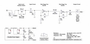
This is a microphone preamplifier (mic preamp) intended for use with ECM (electret condenser microphone) capsules.
Zin (input impedance) is about 25k. Gain is approximately 500, achieved in two stages. Zout (output impedance) is insignificant, or else the value of R6. The output level is approximately line-level (nominal 1 volt), suitable for driving an amplifier directly, or a mixer or other device. The output is not suitable for driving headphones directly, a headphone amp should be used.
Parts have been kept to a minimum, the intention being to let the specified OPA2134 do the work. The OPA2134 is chosen not for its high input impedance (which here doesn't matter), but for its low bias current, high frequency rolloff around 100kHz, and its suitability for use with low impedance circuits.
CIRCUIT NOTES:
Rv1 is the volume control, and together with R1 sets the input impedance, which is the parallel value of Rv1 and R1 (Rv1 || R1), about 25k. Input impedance changes (increases) with the use of the S1 input level selector switch, but the change doesn't affect circuit operation.
Switch S1 together with Rlevel forms an input level selector. S1 "On" bypasses Rlevel for full input from Rv1. S1 "Off" puts Rlevel into the circuit, cutting the input level by about 50%. This is to allow for the different output levels of different ECM capsules, or different ECM capsule circuits.
C1 blocks DC, and together with R1 forms a high-pass (bass rolloff) filter that rolls off low frequencies below about 20 Hz.
U1a is the first gain stage.
R2 and R3 together set the gain for U1a, which here is about 22. Gain = (R2 / R3) +1.
Rcomp is a compensation resistor intended to minimize the DC error caused by bias current (common to all op amps). Ordinarily low-value bias compensation resistors might be omitted, but in this case the OPA2134 data sheet is absolutely freaky on the subject so what the heck.
U1b, R4, and R5 form the second gain stage, operation is the same as the first gain stage.
R6 protects against the effects of capacitance in a following circuit.
Cx is a "maybe" capacitor. Except for Rcomp, errors common to all op amps have been ignored in this circuit, allowing them to be cumulative. This doesn't affect circuit operation, but it does mean there can be significant DC error at the output, due to the high (in audio terms) circuit gain.
It's expected that any following circuit or device will have a capacitor ("AC coupled") input, which will block DC and make the errors unimportant. But if this is not known to be the case then Cx should be included. For output capacitors, when in doubt use 470uF as indicated on the schematic.
WIRING NOTE:
Observe the rule of not mixing the audio signal with the much larger power supply voltages, which can result in distortion. To avoid this, do not run a ground bus (a single, continuous wire) serving both audio and power.
Instead, establish a single "star ground" point very close to the power transformer or battery(s). Run power supply and audio grounds separately to this point, allowing audio and power to mix only at the one point. At this point distortions still occur, but they become insignificant, swamped by the relatively huge voltages and currents of the power supply.
This also means not grounding the input or output jack(s) to the chassis, which is at power supply ground (as opposed to audio ground). The rule is always to keep the audio signal on a clean, separate path of its own.
PARTS NOTE:
At this writing the OPA2134 is available for 3 bucks apiece, shipping included, USA shipper, from here (among many other suppliers): 1 x OPA2134PA OPA2134 2134 Hi Perf Op Amp IC USA Seller Free Shipping | eBay
.
Maybe I used the wrong word. Maybe I shouldn't have said anon, maybe I should have said eventually. Well, be all as it may, my contribution to the pile:
This is a microphone preamplifier (mic preamp) intended for use with ECM (electret condenser microphone) capsules.
Zin (input impedance) is about 25k. Gain is approximately 500, achieved in two stages. Zout (output impedance) is insignificant, or else the value of R6. The output level is approximately line-level (nominal 1 volt), suitable for driving an amplifier directly, or a mixer or other device. The output is not suitable for driving headphones directly, a headphone amp should be used.
Parts have been kept to a minimum, the intention being to let the specified OPA2134 do the work. The OPA2134 is chosen not for its high input impedance (which here doesn't matter), but for its low bias current, high frequency rolloff around 100kHz, and its suitability for use with low impedance circuits.
CIRCUIT NOTES:
Rv1 is the volume control, and together with R1 sets the input impedance, which is the parallel value of Rv1 and R1 (Rv1 || R1), about 25k. Input impedance changes (increases) with the use of the S1 input level selector switch, but the change doesn't affect circuit operation.
Switch S1 together with Rlevel forms an input level selector. S1 "On" bypasses Rlevel for full input from Rv1. S1 "Off" puts Rlevel into the circuit, cutting the input level by about 50%. This is to allow for the different output levels of different ECM capsules, or different ECM capsule circuits.
C1 blocks DC, and together with R1 forms a high-pass (bass rolloff) filter that rolls off low frequencies below about 20 Hz.
U1a is the first gain stage.
R2 and R3 together set the gain for U1a, which here is about 22. Gain = (R2 / R3) +1.
Rcomp is a compensation resistor intended to minimize the DC error caused by bias current (common to all op amps). Ordinarily low-value bias compensation resistors might be omitted, but in this case the OPA2134 data sheet is absolutely freaky on the subject so what the heck.
U1b, R4, and R5 form the second gain stage, operation is the same as the first gain stage.
R6 protects against the effects of capacitance in a following circuit.
Cx is a "maybe" capacitor. Except for Rcomp, errors common to all op amps have been ignored in this circuit, allowing them to be cumulative. This doesn't affect circuit operation, but it does mean there can be significant DC error at the output, due to the high (in audio terms) circuit gain.
It's expected that any following circuit or device will have a capacitor ("AC coupled") input, which will block DC and make the errors unimportant. But if this is not known to be the case then Cx should be included. For output capacitors, when in doubt use 470uF as indicated on the schematic.
WIRING NOTE:
Observe the rule of not mixing the audio signal with the much larger power supply voltages, which can result in distortion. To avoid this, do not run a ground bus (a single, continuous wire) serving both audio and power.
Instead, establish a single "star ground" point very close to the power transformer or battery(s). Run power supply and audio grounds separately to this point, allowing audio and power to mix only at the one point. At this point distortions still occur, but they become insignificant, swamped by the relatively huge voltages and currents of the power supply.
This also means not grounding the input or output jack(s) to the chassis, which is at power supply ground (as opposed to audio ground). The rule is always to keep the audio signal on a clean, separate path of its own.
PARTS NOTE:
At this writing the OPA2134 is available for 3 bucks apiece, shipping included, USA shipper, from here (among many other suppliers): 1 x OPA2134PA OPA2134 2134 Hi Perf Op Amp IC USA Seller Free Shipping | eBay
.
Attachments
Last edited:
Wow, this is quite interesting and multi-detailed! Sorry it has taken me a while to reply (and thank you!), but I have spent the past number of days completing rather complicated arrangements to take care of my home responsibilities in advance of my trip to Taiwan to see my wife and meet new relatives. I am there now for a bit, and let me tell you, it is one of the best places on earth to eat!
I have one question regarding this circuit, and I am probably just a bit disfunctional from jetlag and missing something very obvious, but I do not see how the capsule gets power. I remember that earlier in this thread that you had suggested that a separate power supply would be better for the capsule, is that the intent here?
Regardless, I am grateful once more to enjoy the benefit of your patient and most informative participation in this thread, you are a mensch!
'
I'm a mensch, this from a guy in Taiwan. And Taiwan is one of the best places on earth to eat, this from a guy who lives in NYC. I'm telling you, the world is topsy-turvy. Well, when was it not.
<< I do not see how the capsule gets power >>
It's not a capsule, it's an IC (integrated circuit), or an op amp (operational amplifier, which is a subset of integrated circuits). How does it get power? You've asked this question more than once, in so many words, and I've answered. Answered, needless to say, with my usual brilliant clarity, and yet you keep asking.
This tells us the real question is not how does the IC get power. The real question is something more basic that's not understood. A classic case of the learner not knowing the right question to ask, while the shower isn't seeing the basis of the learner's confusion.
Sooo let's get basic. Which before anything else means stop thinking about power supplies because they're not the subject right now. Power supplies are one thing, amplifiers are another thing, and they have nothing to do with each other. That's right, nothing. As far as an amplifier is concerned power just appears magically out of space. Don't even speak of power supplies. And amplifiers in the same sentence, keep them separate in your mind.
Yes, I know that power supplies are often shown on a schematic right along with the amplifier they power. But this is only a convenience, not a reality. Power supplies are amplifiers are always different, they are never the same, and this is a fact to be kept clearly in mind at all times.
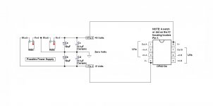
Having accomplished that, we now put power supplies and amplifiers together. Ain't electronics fun? Look at the first illustration below (which obviously is not to scale). The OPA2134 is the same OPA2134 appearing in the previous post 65. Not similar-to, the same. The power supply also is the same as in post 65, not similar-to, the same.
NEVER MIND that this particular power supply is constructed out of batteries. It could just as well be constructed out of nuclear reactors and the result would be the same. Remember how power appears magically out of space? It appears at the points labeled "Pin 8," and "Pin 4" on the power supply, and those two points are all the amplifier cares, or needs to know, about.
<< I do not see how the capsule gets power >>
It's still not a capsule, but it gets power by the power supply being connected to the IC's pins 8 and 4, as shown and as the manufacturer specifies.
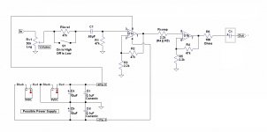
But wait, there's more. Look at the second illustration below. This too is the same as in post 65...so OK, so not the same, so similar, because I've done some editing.
Editing in pins 8 and 4, the pins that connect to the power supply. I've also drawn in the connecting wires, which I think might show why these connections are usually omitted from schematics: with several ICs things can get messy.
So pins 8 and 4 deliver power to U1a, what about U1b? U1a and U1b are internally connected, they both receive power from the same pins 8 and 4.
Sooo how we doing so far?
.
I'm a mensch, this from a guy in Taiwan. And Taiwan is one of the best places on earth to eat, this from a guy who lives in NYC. I'm telling you, the world is topsy-turvy. Well, when was it not.
<< I do not see how the capsule gets power >>
It's not a capsule, it's an IC (integrated circuit), or an op amp (operational amplifier, which is a subset of integrated circuits). How does it get power? You've asked this question more than once, in so many words, and I've answered. Answered, needless to say, with my usual brilliant clarity, and yet you keep asking.
This tells us the real question is not how does the IC get power. The real question is something more basic that's not understood. A classic case of the learner not knowing the right question to ask, while the shower isn't seeing the basis of the learner's confusion.
Sooo let's get basic. Which before anything else means stop thinking about power supplies because they're not the subject right now. Power supplies are one thing, amplifiers are another thing, and they have nothing to do with each other. That's right, nothing. As far as an amplifier is concerned power just appears magically out of space. Don't even speak of power supplies. And amplifiers in the same sentence, keep them separate in your mind.
Yes, I know that power supplies are often shown on a schematic right along with the amplifier they power. But this is only a convenience, not a reality. Power supplies are amplifiers are always different, they are never the same, and this is a fact to be kept clearly in mind at all times.
Having accomplished that, we now put power supplies and amplifiers together. Ain't electronics fun? Look at the first illustration below (which obviously is not to scale). The OPA2134 is the same OPA2134 appearing in the previous post 65. Not similar-to, the same. The power supply also is the same as in post 65, not similar-to, the same.
NEVER MIND that this particular power supply is constructed out of batteries. It could just as well be constructed out of nuclear reactors and the result would be the same. Remember how power appears magically out of space? It appears at the points labeled "Pin 8," and "Pin 4" on the power supply, and those two points are all the amplifier cares, or needs to know, about.
<< I do not see how the capsule gets power >>
It's still not a capsule, but it gets power by the power supply being connected to the IC's pins 8 and 4, as shown and as the manufacturer specifies.
But wait, there's more. Look at the second illustration below. This too is the same as in post 65...so OK, so not the same, so similar, because I've done some editing.
Editing in pins 8 and 4, the pins that connect to the power supply. I've also drawn in the connecting wires, which I think might show why these connections are usually omitted from schematics: with several ICs things can get messy.
So pins 8 and 4 deliver power to U1a, what about U1b? U1a and U1b are internally connected, they both receive power from the same pins 8 and 4.
Sooo how we doing so far?
.
Attachments
Last edited:
.
And having gone through all that my own thinking becomes clear (as clear as it ever gets) and I see the source of your confusion.
All the amplifier (or whatever) circuits you've looked at always have a power supply included, so you've come to think of the amplifier circuit and the power supply as one, yes? Of course yes.
But now this cloud is passing, yes? Also of course yes because now it becomes clear that amplifiers = apples, power supplies = oranges, and never the twain shall meet 'til you hold your breath, urgently implore divine intervention, and plug the thing in (which is how everybody does it). Sooo the light has dawned...er...yes...?
.
Last edited:
.
By the way, one power supply can, and very often does, supply power for any number or audio circuits: preamps, mixers, microphones, equalizers, whatever. <~ key fact, probably
.
By the way, one power supply can, and very often does, supply power for any number or audio circuits: preamps, mixers, microphones, equalizers, whatever. <~ key fact, probably
.
I think that jetlag must be eating the part of my brain responsible for clarity (not a profound place to begin with). Perhaps if I explain what I think I understand, it will reveal where my thinking is befuddled (although, my ex-wives would likely offer the opinion that that is the only thinking I am capable of, but I digress...).
As I understand it, current, like water, flows in one direction, which may branch and divert, but does not flow upstream without being actively acted upon.
In the circuit OP2134 above (which I am most impressed by as a model of clarity of illustration and flexible utility), current flows from its source to power the opamp U1A/B. Current flows from U1A to U1B as well as to a feedback loop and to ground. From U1B it flows into a feedback loop and ground as well as to the circuit output. That is what seems clear to me.
I believe I also see that C1 serves to block DC at the same time that it allows signal from the capsule input device (in the form of voltage) to proceed into the circuit.
I see that the the input device has its output connected into the circuit and to ground through Rv1.
It is at this point that clarity eludes me. I don't recognize where the flow of current into the capsule as you illustrated, for example, in post 41 comes from ( did not review all of the above, but that one seemed clear to me, so I cite it for that reason).
Please allow me once again to express my appreciation for you patient explications.
As a NYC-based musician (though not of that fair city by birth), it is inevitable to pick up certain expressions that have a unique meaning not associated with my own cultural upbringing (rural Texas). It is wonderful to find a one-word expression that can convey broad yet specific meaning, and the term "mensch" is most applicable here. I mean it.
Last edited:
.
Some things to know:
OP AMPS:
No current flows into or out of an op amp's inputs. This is theory that we, for convenience, take as fact.
Both inputs of an op amp are always at the same voltage. Another theory/fact convenience.
ELECTRICAL:
Voltage does not flow, it has no physical existence. Its engineering name is electromotive force (electro - motive - force), and it is, in fact, a force that causes motion in an electrical context. Motion in what, what moves? See next.
Current does flow, it does have physical existence--or close enough (more theory/fact). Current is the "stuff" of electricity that does actual work, such as moving a speaker cone.
Voltage and current are two sides of the same coin. You can't have one without the other, and if you do have one, then you have the other.
AUDIO CIRCUITS:
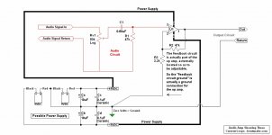
All audio circuits consist of three distinct, complete circuits, or better still, loops. The meeting point for these 3 loops is the op amp, which separates them and controls their interaction.
1. The power supply (loop), which as far as the op amp is concerned is simply a source of infinite current at a given voltage. "Power" is a convenient word indicating that both voltage and current are being discussed at the same time.
2. The input circuit (loop), which signals the op amp what to do with the infinite power available from the power supply.
3. The output circuit (loop). The op amp creates an output circuit by re-routing a controlled portion of the power supply's infinite power into this third loop, which is what we wanted in the first place, and the whole reason we're going through all this.
In all three case what goes out must come in. Not in a philosophical sense, but right here, right now. Current flow from the audio source always returns (loops back) to its origin, and the same for the other two circuits. Ideally the current flows will never mix with each other, haha we wish, because when they do the result is distortion. All circuits have at least some distortion.
THE CRITICAL POINT:
Referring to the circuit in post 65, the critical point here is pin 3 of the op amp, the non-inverting input.
Note in number 2 above, the audio input "signals the op amp what to do with the infinite power available from the power supply." This happens at pin 3. This single point is where we want the audio source voltage (force) to control the op amp without being itself affected.
Still referring to the complete circuit in post #65. Right, the audio signal, which is a current compelled by voltage, passes unimpeded through C1, then through R1, and into ground. We consider that at ground all currents loop back to their origin.
This means there must be voltage at the top of R1, and this voltage is the only thing we care abut.
No current flows into the op amp. Rather, voltage is applied to the input pin. And now we're simply into how op amps work. A voltage applied to the input causes a greater voltage to appear at the output.
Sooo how we doing?
.
Some things to know:
OP AMPS:
No current flows into or out of an op amp's inputs. This is theory that we, for convenience, take as fact.
Both inputs of an op amp are always at the same voltage. Another theory/fact convenience.
ELECTRICAL:
Voltage does not flow, it has no physical existence. Its engineering name is electromotive force (electro - motive - force), and it is, in fact, a force that causes motion in an electrical context. Motion in what, what moves? See next.
Current does flow, it does have physical existence--or close enough (more theory/fact). Current is the "stuff" of electricity that does actual work, such as moving a speaker cone.
Voltage and current are two sides of the same coin. You can't have one without the other, and if you do have one, then you have the other.
AUDIO CIRCUITS:
All audio circuits consist of three distinct, complete circuits, or better still, loops. The meeting point for these 3 loops is the op amp, which separates them and controls their interaction.
1. The power supply (loop), which as far as the op amp is concerned is simply a source of infinite current at a given voltage. "Power" is a convenient word indicating that both voltage and current are being discussed at the same time.
2. The input circuit (loop), which signals the op amp what to do with the infinite power available from the power supply.
3. The output circuit (loop). The op amp creates an output circuit by re-routing a controlled portion of the power supply's infinite power into this third loop, which is what we wanted in the first place, and the whole reason we're going through all this.
In all three case what goes out must come in. Not in a philosophical sense, but right here, right now. Current flow from the audio source always returns (loops back) to its origin, and the same for the other two circuits. Ideally the current flows will never mix with each other, haha we wish, because when they do the result is distortion. All circuits have at least some distortion.
THE CRITICAL POINT:
Referring to the circuit in post 65, the critical point here is pin 3 of the op amp, the non-inverting input.
Note in number 2 above, the audio input "signals the op amp what to do with the infinite power available from the power supply." This happens at pin 3. This single point is where we want the audio source voltage (force) to control the op amp without being itself affected.
In the circuit OP2134 above...current flows from its source to power the opamp U1A/B. Current flows from U1A to U1B as well as to a feedback loop and to ground. From U1B it flows into a feedback loop and ground as well as to the circuit output. That is what seems clear to me.
I believe I also see that C1 serves to block DC at the same time that it allows signal from the capsule input device (in the form of voltage) to proceed into the circuit.
I see that the the input device has its output connected into the circuit and to ground through Rv1.
It is at this point that clarity eludes me...
Still referring to the complete circuit in post #65. Right, the audio signal, which is a current compelled by voltage, passes unimpeded through C1, then through R1, and into ground. We consider that at ground all currents loop back to their origin.
This means there must be voltage at the top of R1, and this voltage is the only thing we care abut.
No current flows into the op amp. Rather, voltage is applied to the input pin. And now we're simply into how op amps work. A voltage applied to the input causes a greater voltage to appear at the output.
Sooo how we doing?
.
Last edited:
.
<< do go on >>
Er...that's all I got. Some of the props got stuck in traffic so we can't do the trapeze bit. What else did you need?
I do have the below illustration, which I hope adds clarity to the "3 current loops" idea (which is a highly scientific principle I made up out of thin air).
Still, somebody did open the refrigerator door, sooo...
Remember that the present subject is a microphone preamp, which is a subset of audio amps in general. Not a power supply (although one is shown, only for convenience), not a microphone, not a stompbox, only an audio amp, itself only, anything else is something different. Don't let apples and oranges start being the same in your thinking, that way madness lies.
<< [the circuit in post 65 is of]...flexible utility >>
Funny you happen to notice this flexible utility, because it's on purpose. The variable is the input circuit, and the OPA2134 has such high Zin that the input circuit can be pretty much anything.
Simplify the input circuit to C1 and R1, and R1 alone sets Zin, which here would be a semi-standard 47k. Higher Zin is achived simply by changing R1 to a higher value. There's no need to change C1 unless Zin gets really high, say 500k or 1meg, in which case C1 should be made 0.33uF.
However, for lower Zin (why?) C1 should be made larger. By the way, its specified value of 0.68uF was selected mainly because that's the largest value Thia Shine carries in Mylar film (I have no association and do not profit blah blah).
None of which, I quickly add, takes anything away from the NE5532, the chip that handles like a sports car and pulls like a truck. Only that the OPA2134 is more suitable, in my opinion, in this particular case. Mainly because of the circuit's gain of about 500, which is astronomically high by audio standards.
In a related matter, since I'm already on my soapbox, I'll do a couple of choruses of my signature song: Do Not Make Things Complicated.
The whole point of little black chips is that the engineers already did the heavy lifting for us, and got paid a lot of money for their fine work. The result is that we just have to fill in a couple of blanks on the form, and there's zero profit in doing anything more.
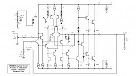
In testimony whereof I post below the factory's partial (only that) schematic of the internal workings of the deservedly popular LM3886, which is typical. Sooo...you're saying what, this is not complicated enough for you?
.
<< do go on >>
Er...that's all I got. Some of the props got stuck in traffic so we can't do the trapeze bit. What else did you need?
I do have the below illustration, which I hope adds clarity to the "3 current loops" idea (which is a highly scientific principle I made up out of thin air).
Still, somebody did open the refrigerator door, sooo...
Remember that the present subject is a microphone preamp, which is a subset of audio amps in general. Not a power supply (although one is shown, only for convenience), not a microphone, not a stompbox, only an audio amp, itself only, anything else is something different. Don't let apples and oranges start being the same in your thinking, that way madness lies.
<< [the circuit in post 65 is of]...flexible utility >>
Funny you happen to notice this flexible utility, because it's on purpose. The variable is the input circuit, and the OPA2134 has such high Zin that the input circuit can be pretty much anything.
Simplify the input circuit to C1 and R1, and R1 alone sets Zin, which here would be a semi-standard 47k. Higher Zin is achived simply by changing R1 to a higher value. There's no need to change C1 unless Zin gets really high, say 500k or 1meg, in which case C1 should be made 0.33uF.
However, for lower Zin (why?) C1 should be made larger. By the way, its specified value of 0.68uF was selected mainly because that's the largest value Thia Shine carries in Mylar film (I have no association and do not profit blah blah).
None of which, I quickly add, takes anything away from the NE5532, the chip that handles like a sports car and pulls like a truck. Only that the OPA2134 is more suitable, in my opinion, in this particular case. Mainly because of the circuit's gain of about 500, which is astronomically high by audio standards.
In a related matter, since I'm already on my soapbox, I'll do a couple of choruses of my signature song: Do Not Make Things Complicated.
The whole point of little black chips is that the engineers already did the heavy lifting for us, and got paid a lot of money for their fine work. The result is that we just have to fill in a couple of blanks on the form, and there's zero profit in doing anything more.
In testimony whereof I post below the factory's partial (only that) schematic of the internal workings of the deservedly popular LM3886, which is typical. Sooo...you're saying what, this is not complicated enough for you?
.
Attachments
Back from the far east, and I must say that you have been so kind to clarify these issues for me and, I hope, others looking to understand the workings of these devices in future. Thanks!
I just found this, which is of interest, and am curious to hear comments
https://www.by-rutgers.nl/ME6211-PRO37R.html
https://www.by-rutgers.nl/ME6211-PRO37R.html
- Status
- Not open for further replies.
- Home
- Amplifiers
- Chip Amps
- input load/mic impedance