Hi,
This may be an obvious question, but I have not been able to find the answer to this. How can you modify the input impedance of a mic preamp circuit? I have searched in as many ways as I could think of, and found no specific answer. As I understand it, the input load should be 10x the impedance of the mic for optimum performance. I would like to build a preamp based on the NE5532, and I am going to experiment with a variety of capsules with very different impedances (680-2200ohm) as well as a piezo film, which ideally requires a 10Mohm load. What part of the circuit determines the load?
Thanks for your patience with my query!
Hi,
Low noise design is not that simple, and no design will
accomodate such a wide range of input impedances.
The NE5534 is lower noise, here is a simple balanced design :
Add supply decoupling capacitors. I'd halve R1 to R5.
If you want lower noise you need transformers or to add
a low impedance low noise front end to the op-amp.
Note input impedance is nominally 600 ohm for mic's,
source resistance is often 100 to 150 ohms, and in
the circuit input impedance is mainly R1 and R2.
Circuits can get far more complicated,
with phantom powering and the like.
rgds, sreten.
Last edited:
Thanks so much for the detailed info! I should be more clear that I intend to breadboard a design to see how different capsules perform. The lowest impedance is a Primo, which IIRC is 600 ohm. These are electret capsules. I would ideally be looking to test how each capsule performs with different loads, so what I need to understand is how to modify that load, what are the elements in the circuit that effect the change in load.
Sreten, Does this mean that by changing the values of R1 and R2, you change the input impedance? Is the input impedance of this circuit 1Kohm? I apologize if I sound ignorant, but there good cause for that!
I notice there is apparently nothing in the power supply connection for the opamp, is that normal?
There may be some mics that require the load impedance to match their own source impedance. The ten times rule would not apply in this case.
Matching of source and load impedances maximises power transfer and at very low signal levels, max power is equivalent to minimising noise.
Matching of source and load impedances maximises power transfer and at very low signal levels, max power is equivalent to minimising noise.
The Power side MUST follow the recommendations of the amp manufacturer unless you have evidence to vary that.I notice there is apparently nothing in the power supply connection for the opamp, is that normal?
Electret capsules often have a driver circuit inside the microphone casing.
These driver circuits "boost" the mic signal and prepare it for driving a line level input and all the cable normally associated with mics.
You really have to find out more about your mic and how to interface it with the other electronics.
These driver circuits "boost" the mic signal and prepare it for driving a line level input and all the cable normally associated with mics.
You really have to find out more about your mic and how to interface it with the other electronics.
.
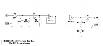
Another way to go is with a buffer. NE5532s are very commonly used this way.
Buffers have unity gain, and extremely high input impedance. For practical purposes a buffer loads the preceding circuit not at all.
I just happen to have a schematic handy. Circuit notes:
R1 and R4 are overcurrent protection for the NE5532, they may be omitted.
C1 is to shunt radio frequencies to ground, it may be omitted.
R2 provides a path to ground for the input signal, to ensure there will be a voltage at the input side of C2. It's there because you usually don't know what the input signal is going to be, and might not be necessary. When R2 is used, then input impedance is the parallel value of R2 and R3 (in this case 50K).
R2 (if used) and R3 may be changed for whatever input impedance is desired. Remember that high values (megs) can multiply noise problems severely.
C2 and R3 are the actual input circuit. Adjust their values for whatever low frequency rolloff might be desired. If R2 is not used, then R3 sets the input impedance.
The amplifying circuit (U1b) is just there to use the other side of the NE5532. It could be another buffer for the other side of a stereo circuit, or whatever you desire (but putting two buffers in series would be pointless).
In a sidebar, I don't know that a piezo source really needs to feed a 10meg input impedance. On the other hand, I can't prove it doesn't. But 0.5meg to 1meg are values more commonly used, as far as I know. Up at 10meg noise problems can be horrendous, every passing breeze can throw things out of whack. Shield everything!
Credit where it's due, the input side of U1a is a rip from Douglas Self. Hope this might be of some interest.
.
Attachments
Last edited:
Thanks for the replies! I have considered a buffer as an option, and I appreciate your explanations, this makes more of this clear to me. I would like the bass roll of to be @30hz, so what mod to R3 would accomplish that?
As I understand the issue with piezo film, the impedance relationship of 10x produces a more linear response, as a match (or ineffectual mismatch) produces a high pass filter effect and other anomalies that give piezos a bad reputation in amplifying stringed instruments (my interest). I am well aware of the shielding requirements, as well. Any clarification in this regard is really welcome!
As I understand the issue with piezo film, the impedance relationship of 10x produces a more linear response, as a match (or ineffectual mismatch) produces a high pass filter effect and other anomalies that give piezos a bad reputation in amplifying stringed instruments (my interest). I am well aware of the shielding requirements, as well. Any clarification in this regard is really welcome!
I notice that the negative output (which #s are these input/outputs on the NE5532, BTW, I don't have the data sheet on me?) feeds a positive input on the NE5532, is that for some kind of feedback? Sorry to be such a pain, I am a musician, and my electronics background was limited and decades ago...
as to the capsules, perhaps some more info would be useful. As far as I can tell, none of these is line level.
3 caps are 600 Ohm (Rs 5.6K), 5vDC operating voltage, circuit current 600uA max (Vcc=5v), all are 3 pin GND Drain Source
1 cap is 680 Ohm, 1.5vDC operating voltage (10v max), current consumption .5mA max (Vs=2.0v RL=680 Ohm, 2 wire (requires Linkwitz mod)
3 caps are 600 Ohm (Rs 5.6K), 5vDC operating voltage, circuit current 600uA max (Vcc=5v), all are 3 pin GND Drain Source
1 cap is 680 Ohm, 1.5vDC operating voltage (10v max), current consumption .5mA max (Vs=2.0v RL=680 Ohm, 2 wire (requires Linkwitz mod)
.
There is no positive or negative output on the NE5532. You're thinking of the inputs, which are correctly called non-inverting (+) and inverting (-). The output is just the output.
You do know that piezos are contact mics, right? After that your understanding of piezo impedance questions is correct, you don't need further explanations. What you do need is to strike a balance.
Ten megs (10,000,000 ohms) is astronomically high in audio terms, and noise problems can be severe. Resistances in the thousands of ohms (K) are much more common, and 1meg is pretty much the limit. So you balance theory against reality and come up with a 1/2 or 1meg input impedance.
Electret capsules are of a muchness. They all run at about 3 volts (BUT CHECK THIS), and current consumption is negligible. All I know of, which is several, wind up with a 2.2K output impedance, which ideally feeds, as you've said, a 22K input impedance. Important thing to know: or more.
"Balanced impedance" applies to tubes (valves, foreigner call them) and radio/telephone circuits. Except, as sreten pointed out, in some cases where manufacturers say different, and then you follow the instructions.
Otherwise, the universal rule is "low impedance feeds high impedance," also as you've said.
By the way, FYI, impedance is simply the AC version of resistance. It's different with AC because capacitors and inductors (any coil of wire) have different characteristics at different frequencies, which is not so with DC--because DC has only one frequency: on.
I really should have modified the schematic I posted to your needs--although come to think of it I don't know your needs, except I'm guessing you want to mic your chello. In any case, with the schematic otherwise as posted, changing C2 to 0.1uF would fulfill your needs.
Getting back to electrets, you might be astonished at the audio quality you get from a 50-cent capsule (or 2 bucks, or whatever). Their downfall is that they need batteries, of course, which means a battery holder someplace nearby. On the other hand, the batteries last pretty much forever. The alternative is phantom power that runs from the amp to the mic, but this is making things perhaps unreasonably complicated.
Expect an output from an electret of about 2 millivolts (0.002v). This require a gain of 400 to get up close to line level, which is nominally 1 volt. Amplifiers expect a line level input, preamplifiers don't.
Piezos have much higher output, about a volt more or less, but this varies wildly with sound level. In neither case can you just run any length of cable you like from your instrument to the amp. Grabbing a figure out of the air, say 20 feet max.
You're going to have to look up your own pin numbers. Google for NE5532 and click any PDF document. Thinking about it, I b'lieve I'll draw up another schematic.
.
Thanks so much for the careful and clear reply, it is very helpful. I am aware that electret capsules are used in DPA mics and other with excellent results, which is why I would like to find a more reasonable cost alternative. Most of the options available are junk or way too $$$.
The 400x gain required = @40dB?
I am aware of the cabling issues with piezos (and yes I know they are contact mics, I've used some variant or other of awful sounding piezos for 40 years). But, there is no reason they must sound as bad as they usually do. This is why I am exploring this option for dealing with them. The potential of the silver films looks excellent, and those that are on the market have a good reputation (though not good enough IMHO).
Last edited:
I am also confused about which version of the NE5532 to use, there are so many, and it is not at all clear to me from the data sheets I have seen (TI's site is down)
.
A voltage gain of 400 is a decibel gain of 52. But amplifiers don't work with decibels, they work with voltage.
Those junk electrets you mention might be worth another look. These things are turned out by automatic machines, and it costs a freakin' fortune to set up the factory, so a certain level of quality can be expected (they have to sell tens of thousands to pay for the factory). Make sure what you're looking at is for audio, not for telephones or intercoms.
In my opinion piezo contact pickups are excellent. But I haven't worked with film, only with hard disks, which by the way are available on eBay.
The downside of piezos is mounting them. I don't think there's any such thing as a cheap cello, so obviously care is needed. Clamp the piezo into a sound hole?
In any case don't think a piezo will avoid or prevent feedback, because it's still a microphone. The only solution to feedback is to stay away from the speakers--or an amp with a notch filter, but now things get complicated again.
I simplify life and NE5532 models by buying from Thai Shine on eBay, I just order what they have. If you're interested, and if this forum allows, here's a link:
1 4W 5, Other IC's items in Thai Shine store on eBay!
Disclosure: I have no association with Thai Shine except sometimes I send them money. In any case an NE5532 is an NE5532. Suffix numbers and letters matter to engineers, but not much to us.
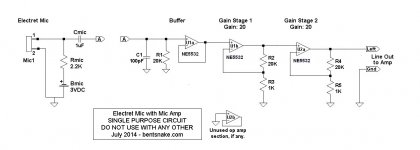
Moving right along, as advertised, here ya go. You're not supposed to start soldering this together this afternoon (although you could, and it would work). This is intended to give you a frame of reference.
Circuit notes:
The two points A are the same point. They're separated only to acknowledge that the mic circuit and amp circuit might be physically separated.
Battery Bmic is chosen to suit the capsule used. Resistor Rmic is expected to be universal, or if not then to suit.
Capacitor Cmic is actually part of the input circuit to U1a. It blocks battery voltage to the amp circuit, and also forms a high pass filter in association with R1. This association between Cmic and R1 is what makes this a "single purpose circuit." Move Cmic over onto the amp board and the whole assembly can be used for anything.
C1 is to shunt radio frequencies to ground. Stage environments can be expected to have a very high level of radio frequencies. As is common practice when dealing with radio frequences, keep the leads as short as possible (this actually applies everywhere).
Op amp U1a is a buffer.
R2 and R3 set the gain for op amp U1b. R4 and R5 set the gain for op amp U2a.
Input impedance as shown is 20K, which is right for both an electrec mic, and for general purpose use. For 50K input impedance make R1 50K, and Cmic 0.22uF. For 500K, make R1 500K, and Cmic 0.1uF. For 1meg, make R1 1meg, and Cmic 0.068uF. The capacitor values are not critical.
Capacitors are film type. This means Mylar film capacitors costing pennies, not the dollars-each stuff that some say you need. Or as you judge best, of course. The most common value available is 100 volt, and these are fine.
Same with resistors, which are 1/4 watt. Metal film does have advantages, and they don't cost all that much more, but they're probably not on the shelf so carbon resistors will do just dandy. By the way, carbon resistors today are far superior to what they once were...I read someplace.
In case of an unused section of op amp, terminate the unused section as shown. With the input grounded the op amp has a unity-gain output of ground, so it does nothing. Connect power to an unused section of op amp as to any other, do not leave it floating.
.
A voltage gain of 400 is a decibel gain of 52. But amplifiers don't work with decibels, they work with voltage.
Those junk electrets you mention might be worth another look. These things are turned out by automatic machines, and it costs a freakin' fortune to set up the factory, so a certain level of quality can be expected (they have to sell tens of thousands to pay for the factory). Make sure what you're looking at is for audio, not for telephones or intercoms.
In my opinion piezo contact pickups are excellent. But I haven't worked with film, only with hard disks, which by the way are available on eBay.
The downside of piezos is mounting them. I don't think there's any such thing as a cheap cello, so obviously care is needed. Clamp the piezo into a sound hole?
In any case don't think a piezo will avoid or prevent feedback, because it's still a microphone. The only solution to feedback is to stay away from the speakers--or an amp with a notch filter, but now things get complicated again.
I simplify life and NE5532 models by buying from Thai Shine on eBay, I just order what they have. If you're interested, and if this forum allows, here's a link:
1 4W 5, Other IC's items in Thai Shine store on eBay!
Disclosure: I have no association with Thai Shine except sometimes I send them money. In any case an NE5532 is an NE5532. Suffix numbers and letters matter to engineers, but not much to us.
Moving right along, as advertised, here ya go. You're not supposed to start soldering this together this afternoon (although you could, and it would work). This is intended to give you a frame of reference.
Circuit notes:
The two points A are the same point. They're separated only to acknowledge that the mic circuit and amp circuit might be physically separated.
Battery Bmic is chosen to suit the capsule used. Resistor Rmic is expected to be universal, or if not then to suit.
Capacitor Cmic is actually part of the input circuit to U1a. It blocks battery voltage to the amp circuit, and also forms a high pass filter in association with R1. This association between Cmic and R1 is what makes this a "single purpose circuit." Move Cmic over onto the amp board and the whole assembly can be used for anything.
C1 is to shunt radio frequencies to ground. Stage environments can be expected to have a very high level of radio frequencies. As is common practice when dealing with radio frequences, keep the leads as short as possible (this actually applies everywhere).
Op amp U1a is a buffer.
R2 and R3 set the gain for op amp U1b. R4 and R5 set the gain for op amp U2a.
Input impedance as shown is 20K, which is right for both an electrec mic, and for general purpose use. For 50K input impedance make R1 50K, and Cmic 0.22uF. For 500K, make R1 500K, and Cmic 0.1uF. For 1meg, make R1 1meg, and Cmic 0.068uF. The capacitor values are not critical.
Capacitors are film type. This means Mylar film capacitors costing pennies, not the dollars-each stuff that some say you need. Or as you judge best, of course. The most common value available is 100 volt, and these are fine.
Same with resistors, which are 1/4 watt. Metal film does have advantages, and they don't cost all that much more, but they're probably not on the shelf so carbon resistors will do just dandy. By the way, carbon resistors today are far superior to what they once were...I read someplace.
In case of an unused section of op amp, terminate the unused section as shown. With the input grounded the op amp has a unity-gain output of ground, so it does nothing. Connect power to an unused section of op amp as to any other, do not leave it floating.
.
Attachments
Last edited:
Thanks so much for all of this info, you are a mensch! Most of the inexpensive electret instrument mics are not made with quality pres, in my experience, and the piezos are awful. They really don't have to be as far as I can tell. Mounting is also an issue, but most people who do this really don't understand what the instrument should sound like. It is a different mindset, but that is kind of off topic.
I have an old Benchmark 4x4 mic pre that uses the NE5432 (the manual that came with it is really an amazing document, lots of research papers, schematics, etc.), and to this day, there aren't a lot cleaner pres out there, hence my interest in this piece for this project. Tried and true, cheap and available. I am considering the OPA627 for the piezo, as it is supposed to deal well with high impedance, but that is a little bit down the pike.
The film sensors handle high physical pressure really well, so placing them under the bridge is a natural, and because of that location, little body resonance is an issue so I don't think that feedback would be a problem at all. I have played in very loud events using DPAs, and was shocked that it worked. Of course, the venue was very large (Radio City) and the tech team world class (MTV music video awards- some years ago ago), so that counts for a lot, but players and situations, this would not hold out. Most of my work is not so important for feedback rejection. I've been using DPA and Sennheiser mics from wireless sets converted for phantom power, and they sound quite good, but there are lots of situations where that is not possible. Mics obviously sound more natural, but there is a need for something better for loud music in small venues.
Looking over this schematic, it appears that this could be made stereo with just one more NE5532 as a second buffer, if I am not mistaken.
Many thanks!
.
<< DPAs >>
Whether any microphone in the universe is worth a thousand dollars, I leave to the individual's judgement. I am willing to say that audio engineers are to microphones as women are to shoes, and musicians are no better. Singers are worse.
<< it appears that this could be made stereo with just one more NE5532 as a second buffer >>
Yes, and this is expected. And by the way, for a power supply you might a look at posts #30 and 31 of this thread, he said with a simper of false modesty:
http://www.diyaudio.com/forums/chip-amps/258539-tda2030-bass-amp-distortion-noise-3.html
<< I am considering the OPA627 for the piezo, as it is supposed to deal well with high impedance... >>
Not to argue but to discuss, the input impedance of the buffer shown is off-scale. Anything hoped to be higher is more in the realm of theory than fact. This is not unique to the NE5532, it's the nature of op amp buffer (unity gain) circuits.
As you know, for over two decades the NE5532 was the top of the line. The result of significance is that any recorded music anywhere in the world had been massaged by dozens of NE5532s. As a matter of fact this continues partly so today, since most studios don't junk their equipment every time a salesman promises new and improved.
The key element of "new and improved" is: does it sound better, or is this a distinction without a difference? It's true that more modern chips have better numbers on the graph, sometimes much better. But whether the sound is any better, or even any different, seems to remain an open question.
<< little body resonance is an issue so I don't think that feedback would be a problem at all >>
I disagree without being able to present an argument, except that with a contact mic the entire body of the instrument becomes a microphone. But your guess is as good as, and possibly a lot better than, mine.
Still it remains that speakers are not placed among the musicians, they're placed down front facing the audience (usually). So the solution remains to stay away from the speakers, or point them somewhere else, anywhere else.
Just to mention it, a venue like Radio City probably has first-class equipment, but it's 20 years old--but still first-class. This means they know all about feedback (universally a problem with live performance), and have switches and knobs to fight it, and more important, expertise. By expertise I mean George, who started out dusting off the vacuum tubes. Of course I'm just guessing here, except about George, there's certainly a George.
<< most people who do this really don't understand what the instrument should sound like >>
Don't say that, or somebody will start asking whether any recorded music sounds anything at all like the real thing. I'm glad this has helped a bit. If you have more problems or questions (you will) I'll certainly be glad to help if I can, as will others.
.
Hi,
Descending into a pointless mess, with no accurate definition
of the transducers involved, or a real question, just waffle.
rgds, sreten.
Descending into a pointless mess, with no accurate definition
of the transducers involved, or a real question, just waffle.
rgds, sreten.
Oops, let me clarify, I meant that no one doing this, playing in a huge venue (everything and everyone is brought in from outside, BTW, you see pretty much the same crew in NYC for all of the video-based music events) with spls like being on a runway when a plane is landing, and make a close mic on an instrument of that sort and make it sound real (natural) the way the player hears it acoustically, not that there aren't amazing recordings. I've heard and played on many. The problem is how to avoid feedback and other signals and get a sound with some space around it, as on the best classical recordings (and jazz): acoustic instruments in acoustically resonant space. This is impossible in the circumstance I mentioned, it is obviously possible with suitable circumstances to make beautiful recordings.
Last edited:
- Status
- Not open for further replies.
- Home
- Amplifiers
- Chip Amps
- input load/mic impedance