.
<< 50k is getting up into the Johnson noise region, yes, if that is the source impedance seen by the stage...Your mic is NOT that. The 50k is parallel to the 5k6. That reduces the source impedance seen by the amplifier to 5k >>
My understanding is otherwise. The short explanation is that the 5.6k resistor doesn't count as part of the buffer circuit, it counts as source.
Being more long winded, the 5.6k (in this case) resistor is load resistor. Its function is to drop whatever might be the operating voltage of the capsule circuit, so a voltage will be present at the capacitor. This voltage is the input to the buffer.
When the buffer "looks back" at the capsule circuit it sees this voltage, accepts it as an input voltage, and does what buffers do.
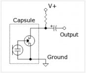
Worth a brief consideration here is the FET (Field Effect Transistor) inside the capsule housing. Panasonic calls this an "FET Impedance Converter." I've attached an illustration from Wikipedia.
FETs are extremely high impedance devices, and here the 5.6k resistor is in parallel. The result is that the FET effectively becomes an open circuit as far as the buffer is concerned, and the buffer sees only the 5.6k resistor.
But it's not a resistor as far as the buffer is concerned, it's source. This capsule puts out about 5millivolts, so the buffer is seeing "a 5millivolt power supply with a Zout of 5.6k." And it's this 5.6k that we multiply by 10...or 7...or 20...or at this point by the winning lottery number that week.
Or of course I might have the whole thing wrong. But that's my story and I'm sticking to it.
.
<< 50k is getting up into the Johnson noise region, yes, if that is the source impedance seen by the stage...Your mic is NOT that. The 50k is parallel to the 5k6. That reduces the source impedance seen by the amplifier to 5k >>
My understanding is otherwise. The short explanation is that the 5.6k resistor doesn't count as part of the buffer circuit, it counts as source.
Being more long winded, the 5.6k (in this case) resistor is load resistor. Its function is to drop whatever might be the operating voltage of the capsule circuit, so a voltage will be present at the capacitor. This voltage is the input to the buffer.
When the buffer "looks back" at the capsule circuit it sees this voltage, accepts it as an input voltage, and does what buffers do.
Worth a brief consideration here is the FET (Field Effect Transistor) inside the capsule housing. Panasonic calls this an "FET Impedance Converter." I've attached an illustration from Wikipedia.
FETs are extremely high impedance devices, and here the 5.6k resistor is in parallel. The result is that the FET effectively becomes an open circuit as far as the buffer is concerned, and the buffer sees only the 5.6k resistor.
But it's not a resistor as far as the buffer is concerned, it's source. This capsule puts out about 5millivolts, so the buffer is seeing "a 5millivolt power supply with a Zout of 5.6k." And it's this 5.6k that we multiply by 10...or 7...or 20...or at this point by the winning lottery number that week.
Or of course I might have the whole thing wrong. But that's my story and I'm sticking to it.
.
Attachments
except that I prefer >20times if the impedances can be selected to achieve that.
50k Rin would suit <2k5 Rs. I can do a lot better than that.
But if I had a 100r Rs feeding a first stage attenuator of 2k I could just achieve 20times.
If the output of that first stage attenuator never exceeds 525r then the second stage must be >= 10k5.
I could use 10k.
The maximum output impedance is 2k6 and that would feed Rin = 52k.
It is just about possible to use passive attenuators in two stages between Rs=100r and Rin=50k without needing buffers to get to that 20times target.
The aikido attenuator is a two stage attenuator that uses three switches to give 1.5dB volume adjustment from -54dB to 0dB AND gives stereo balance control.
BUT !!! the designer forgot about the interstage impedances and the control function/slope falls apart due to using the wrong resistor values.
Changing the resistor values of the first stage cured the error and makes a very good stepped stereo balancing and vol pot in a cheap package.
Your mic to receiver needs similar assessment.
What can the mic drive?
How loud/quiet can it go?
What gain is required in the receiver?
How much noise can it tolerate?
Does any part need long cables?
Does any part need balanced impedance connections to minimise interference?
All these are interlinked
Your points are valid, but actually I've addressed them in what turned out to be this somewhat long thread. Addressed them, at least, according to my understanding.
That is, except for volume control. I thought that a needless complication for the present.
.
.
What occurs to me is that the difference in performance between 10V/10k and 5V/5k6 in sensitivity is that the 5V/5k6 is 1.9% less sensitive, equal for the noise floor, and has a 0.8% increase in S/N over the 10V/10k. It seems to me that such a difference is not significant for my purpose at the moment to suggest the higher load and voltage, which would also seem to put it "more in the middle", as well.
So, now I need to figure the high pass at 40hz and limit voltage (from however it will be powered) going to the capsule to 5V.
It is very interesting comparing these figures to the equivalent DPA product.
So, now I need to figure the high pass at 40hz and limit voltage (from however it will be powered) going to the capsule to 5V.
It is very interesting comparing these figures to the equivalent DPA product.
I know that this has been a long thread for such a topic, but for a newbie like me, such information is otherwise not addressed in an easy to find source on these boards, so I think it is all to the good. And, I personally am very grateful for the discussion and its tone.
.
Well, I suppose it had to come to this. Then let it be so. But I'm still going to waffle.
Volume control: I'm not going to give you one. True you can hang a pot (potentiometer = variable resistor) in some convenient place and use it, but in an electronic circuit everything affects everything, so what's convenient is not always what's wise. And you want to test microphones, which is a case that allows for very little messing around.
The unfortunate result is that things can get a wee bit complicated. But you have a perfectly good volume control on your preamp, so all that's really needed is to avoid overloading your preamp's line-in input.
So instead of a volume control, you get to attenuate. (attenuate [verb]: Attenuate - Definition and More from the Free Merriam-Webster Dictionary )
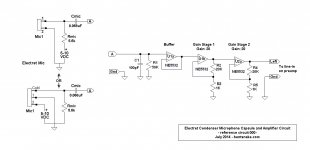
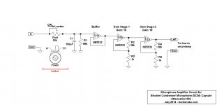
The circuit I've attached has no attenuation. It's a compendium, more or less, of what's been discussed before, and is intended as a reference point.
The circuit has the 40 Hz rolloff you mentioned, but I still suggest just using a 1uF capacitor for all testing. For your present purpose rolling off bass seems beside the point to me. The important thing is just to block the capsule power supply voltage from the NE5532 circuit.
To power the capsule, I'd think a battery(s) would be the best way by far. Otherwise you're into power supplies and additional wiring, with things getting my least favorite thing: complicated.
At once you wonder: but the two grounds, the battery circuit ground, and the amp circuit ground, are at different voltages, so what do I do about the grounds?
You connect them together. The battery circuit is isolated unto itself, so its ground will "float" higher or lower to match the amp's power supply ground, and that's that.
So here's the reference schematic. Tomorrow, or when I have a chance to check my figures, I'll post additional.
.
Well, I suppose it had to come to this. Then let it be so. But I'm still going to waffle.
Volume control: I'm not going to give you one. True you can hang a pot (potentiometer = variable resistor) in some convenient place and use it, but in an electronic circuit everything affects everything, so what's convenient is not always what's wise. And you want to test microphones, which is a case that allows for very little messing around.
The unfortunate result is that things can get a wee bit complicated. But you have a perfectly good volume control on your preamp, so all that's really needed is to avoid overloading your preamp's line-in input.
So instead of a volume control, you get to attenuate. (attenuate [verb]: Attenuate - Definition and More from the Free Merriam-Webster Dictionary )
The circuit I've attached has no attenuation. It's a compendium, more or less, of what's been discussed before, and is intended as a reference point.
The circuit has the 40 Hz rolloff you mentioned, but I still suggest just using a 1uF capacitor for all testing. For your present purpose rolling off bass seems beside the point to me. The important thing is just to block the capsule power supply voltage from the NE5532 circuit.
To power the capsule, I'd think a battery(s) would be the best way by far. Otherwise you're into power supplies and additional wiring, with things getting my least favorite thing: complicated.
At once you wonder: but the two grounds, the battery circuit ground, and the amp circuit ground, are at different voltages, so what do I do about the grounds?
You connect them together. The battery circuit is isolated unto itself, so its ground will "float" higher or lower to match the amp's power supply ground, and that's that.
So here's the reference schematic. Tomorrow, or when I have a chance to check my figures, I'll post additional.
.
Attachments
I agree that for my purpose that a volume control is an addition and unnecessary complication, as would be tone controls.
Thanks so much for your patient and thorough explanations.
Thanks so much for your patient and thorough explanations.
<< I agree that for my purpose that a volume control is an addition and unnecessary complication... >>
It would be, if it weren't for that gain of 400, I belatedly realized.
The working number I use for ECM capsule output is 200 millivolts. But the data sheet you posted shows 500 millivolts output (if I read it correctly). This 3 millivolts times 400 is significant, it can overload your preamp line-in circuit, causing distortion and making the whole thing an exercise in futility.
Sooo attenuation will occur. Sec.
.
As advertised:
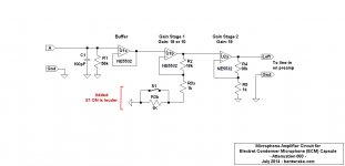
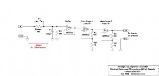
ERRATA: In the circuit I posted earlier I neglected to change the resistor values to standard values. That's corrected in the new Reference 000.
Following Reference 000 there are three circuits. WAIT! Please don't get excited and start cussin' me, shouting things like, "Pick the one I need? How am I supposed to pick the one I need?! If I knew what I needed, I wouldn't be asking you in the first place!"
Let us proceed calmly. The question now has nothing to do with electronics, it's purely mechanical. The parts we use are small and (preferably) close together, and mistakes are regrettably easy to make. Sooo...which circuit do you find the least irritating to build?
Attenuation 001 would be my own choice, unless I had compelling reasons to do otherwise. It simply decreases the level of the incoming signal, unless the switch is closed, and then it does nothing.
Attenuation 002 is the same thing, but adjustable. Adjustable is nice, but the pot body probably needs grounding, and generally things are a bit more mechanically complex.
Attenuation 003 has the theoretical advantage of not affecting the incoming signal in any way. It's after the buffer, at which point you're working with a low-level, low impedance signal, which is home free for an IC (integrated circuit). But I don't think the theoretical advantages accomplish anything in the real universe, and the thing might be a bit of a pain to wire up.
All three circuits do approximately the same thing--allowing for using standard component values--so it's just a question of which you think might be easier to build. And then, in any case we're not talking about wiring up the starship Enterprise. You could easily make a case for just flipping a coin--I guess you'd have to flip it twice.
.
As advertised:
ERRATA: In the circuit I posted earlier I neglected to change the resistor values to standard values. That's corrected in the new Reference 000.
Following Reference 000 there are three circuits. WAIT! Please don't get excited and start cussin' me, shouting things like, "Pick the one I need? How am I supposed to pick the one I need?! If I knew what I needed, I wouldn't be asking you in the first place!"
Let us proceed calmly. The question now has nothing to do with electronics, it's purely mechanical. The parts we use are small and (preferably) close together, and mistakes are regrettably easy to make. Sooo...which circuit do you find the least irritating to build?
Attenuation 001 would be my own choice, unless I had compelling reasons to do otherwise. It simply decreases the level of the incoming signal, unless the switch is closed, and then it does nothing.
Attenuation 002 is the same thing, but adjustable. Adjustable is nice, but the pot body probably needs grounding, and generally things are a bit more mechanically complex.
Attenuation 003 has the theoretical advantage of not affecting the incoming signal in any way. It's after the buffer, at which point you're working with a low-level, low impedance signal, which is home free for an IC (integrated circuit). But I don't think the theoretical advantages accomplish anything in the real universe, and the thing might be a bit of a pain to wire up.
All three circuits do approximately the same thing--allowing for using standard component values--so it's just a question of which you think might be easier to build. And then, in any case we're not talking about wiring up the starship Enterprise. You could easily make a case for just flipping a coin--I guess you'd have to flip it twice.
.
Attachments
.
<< a couple of more informative pdfs on Primos mic >>
Strangely, what you call the Primos mic also seems to be Scott Helmke's Alice mic. Same schematic: Alice Microphone
The audio part of the mic is JLI's Transound TSB-165A capsule. Data here: TSB-165A
Looking at the capsule data, you might notice a certain of-a-muchness. I'm trying to suggest an idea, there. No doubt there's a difference between a 50 cent capsule and a $7 capsule...or...hmmm.
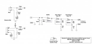
The circuit shown by Mr. Helmke--or whoever--is a mic amp only in passing. It's main purpose is to convert the mic's single output (true of all mics) into a dual output that will travel on a "balanced line." (hence the XLR connectors)
Briefly and not very clearly, with a balanced line the mic's single output is first split and amplified, then one of the signals from the split is sent down the line as-is, but the other is flipped to be out of phase.
At the receiving end, the flipped signal is flipped again, so it's in-phase, and the two signals are combined. The resulting single signal is then sent on to a buffer, preamp, whatever, the same circuits I've posted in this thread, plus or minus some gain as required by that particular system.
It's important to realize that balanced lines, and their associated XLR connectors, have nothing to do with audio directly. It's all about reducing the noise picked up by the connecting cables, and only that.
.
<< a couple of more informative pdfs on Primos mic >>
Strangely, what you call the Primos mic also seems to be Scott Helmke's Alice mic. Same schematic: Alice Microphone
The audio part of the mic is JLI's Transound TSB-165A capsule. Data here: TSB-165A
Looking at the capsule data, you might notice a certain of-a-muchness. I'm trying to suggest an idea, there. No doubt there's a difference between a 50 cent capsule and a $7 capsule...or...hmmm.
The circuit shown by Mr. Helmke--or whoever--is a mic amp only in passing. It's main purpose is to convert the mic's single output (true of all mics) into a dual output that will travel on a "balanced line." (hence the XLR connectors)
Briefly and not very clearly, with a balanced line the mic's single output is first split and amplified, then one of the signals from the split is sent down the line as-is, but the other is flipped to be out of phase.
At the receiving end, the flipped signal is flipped again, so it's in-phase, and the two signals are combined. The resulting single signal is then sent on to a buffer, preamp, whatever, the same circuits I've posted in this thread, plus or minus some gain as required by that particular system.
It's important to realize that balanced lines, and their associated XLR connectors, have nothing to do with audio directly. It's all about reducing the noise picked up by the connecting cables, and only that.
.
I just included those iterations of treatments of Primo capsules as examples of other treatments, sorry if that was a bit OT and hence, a distraction. In comparing the data sheets between the "Alice" capsule and the Primos, there seems a big difference in performance. The TSB-165A has significantly higher impedance, is 17% less sensitive, has 19% lower S/N ratio, and has between 13.3% and 16.6% lower SPL handling capacity (depending on which Primo capsule you compare it to), and is both lower voltage and has a smaller voltage range. Of course, this is just from the published data, FWIW. To me, those figures are enough to not consider them, especially for the $$. The Primos are not cheap, either, but there is no comparison of performance and value. Ditto the panasonic-types. I have no business interest or relationship to Primo, BTW, just a favorably impressed observer. Thanks again for the link re NE5432, great price and fast delivery.
I really appreciate all of the effort in creating these clear examples of possible circuits and the explanations of the thinking behind them. I hope and trust that others over time will be equally illuminated.
I really appreciate all of the effort in creating these clear examples of possible circuits and the explanations of the thinking behind them. I hope and trust that others over time will be equally illuminated.
Last edited:
.
<< ...17% less sensitive, has 19% lower S/N ratio, and has between 13.3% and 16.6% lower SPL handling capacity... >>>
I'm absolutely making things up out of thin air here, but it's well to remember that electronics is not a precise discipline. Or maybe it is at NASA. but not in the 20-20kHz range.
As an example, assume two resistors of the same value, each rated at 5% tolerance. Side by side in a circuit there could be an error of 10% between them. Tolerances for capacitors are worse, and this applies to every component in every circuit.
As you surmise, I mean to suggest that some things are more in the marketing department's skillful numbers-massaging than the engineer's calculations. But then, I have no evidence to offer, it's only my supposition.
<< I really appreciate all of the effort... >>
Heck, you're welcome, glad to help out a bit.
.
I totally agree about these data sheets, which is why I mentioned FWIW. It's the same with statistics and polling. Sometimes the answer you get depends on the question you asked. Sometimes, on the questions you didn't... I will say that it seems that the real world experience of many using the Panasonic and Primo capsules seems to bear out the data sheets pretty well. Of course, that is anecdotal and not measured and number-driven...
Primo seems to be very engineer-driven, from what I surmise in talking with folks over there, and in the next couple of weeks, I hope to start doing some testing. I shall report the results, FWIW
Primo seems to be very engineer-driven, from what I surmise in talking with folks over there, and in the next couple of weeks, I hope to start doing some testing. I shall report the results, FWIW
Last edited:
1 more stupid question: it is not clear to me where the power (9V, P48V) enters these circuits, could you please illuminate me?
Thx!!
Thx!!
.
As advertised:
ERRATA: In the circuit I posted earlier I neglected to change the resistor values to standard values. That's corrected in the new Reference 000.
Following Reference 000 there are three circuits. WAIT! Please don't get excited and start cussin' me, shouting things like, "Pick the one I need? How am I supposed to pick the one I need?! If I knew what I needed, I wouldn't be asking you in the first place!"
Let us proceed calmly. The question now has nothing to do with electronics, it's purely mechanical. The parts we use are small and (preferably) close together, and mistakes are regrettably easy to make. Sooo...which circuit do you find the least irritating to build?
Attenuation 001 would be my own choice, unless I had compelling reasons to do otherwise. It simply decreases the level of the incoming signal, unless the switch is closed, and then it does nothing.
Attenuation 002 is the same thing, but adjustable. Adjustable is nice, but the pot body probably needs grounding, and generally things are a bit more mechanically complex.
Attenuation 003 has the theoretical advantage of not affecting the incoming signal in any way. It's after the buffer, at which point you're working with a low-level, low impedance signal, which is home free for an IC (integrated circuit). But I don't think the theoretical advantages accomplish anything in the real universe, and the thing might be a bit of a pain to wire up.
All three circuits do approximately the same thing--allowing for using standard component values--so it's just a question of which you think might be easier to build. And then, in any case we're not talking about wiring up the starship Enterprise. You could easily make a case for just flipping a coin--I guess you'd have to flip it twice.
.
.
<< 1 more stupid question: it is not clear to me where the power (9V, P48V) enters these circuits, could you please illuminate me? >>
Whoa! Long time no C. Things are good, I hope & trust.
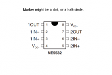
Not stupid at all, how are you supposed to know? Power connections are often left off of a schematic just to avoid having more lines running all over the place. On the NE5532 the connections are positive to pin 8, negative to pin 4. Here's the data sheet just in case: http://www.ti.com/lit/gpn/ne5532
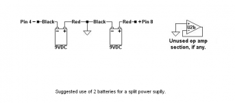
Below I'm posting an el quickO illustration of which pin is which.
<< the power (9V, P48V) >>
My heart sinks. You intend to run a single-supply circuit, using just one 9 volt battery? Could you possibly not? Posted below is how to hook up two batteries.
I'm not even sure the NE5532 will run on 9 volts, which is +/-4.5 volts. The circuit is more complicated (to split the 9 volts into +/-4.5 volts, for one thing), and performance is less. With the sheer quantity (as opposed to volume) of sound that a cello puts out I have deep misgivings about using a single supply.
<< P48V >>
And 48 volt phantom power to boot? Then I'm off the hook because I know nothing on the subject, since I don't use it.
But I don't think any electret capsule uses 48 volts, or anything close to it. Would you consider using batteries? Electret capsules draw so little power that the battery life is pretty much their shelf life--as long as you remember to turn things off.
.
<< 1 more stupid question: it is not clear to me where the power (9V, P48V) enters these circuits, could you please illuminate me? >>
Whoa! Long time no C. Things are good, I hope & trust.
Not stupid at all, how are you supposed to know? Power connections are often left off of a schematic just to avoid having more lines running all over the place. On the NE5532 the connections are positive to pin 8, negative to pin 4. Here's the data sheet just in case: http://www.ti.com/lit/gpn/ne5532
Below I'm posting an el quickO illustration of which pin is which.
<< the power (9V, P48V) >>
My heart sinks. You intend to run a single-supply circuit, using just one 9 volt battery? Could you possibly not? Posted below is how to hook up two batteries.
I'm not even sure the NE5532 will run on 9 volts, which is +/-4.5 volts. The circuit is more complicated (to split the 9 volts into +/-4.5 volts, for one thing), and performance is less. With the sheer quantity (as opposed to volume) of sound that a cello puts out I have deep misgivings about using a single supply.
<< P48V >>
And 48 volt phantom power to boot? Then I'm off the hook because I know nothing on the subject, since I don't use it.
But I don't think any electret capsule uses 48 volts, or anything close to it. Would you consider using batteries? Electret capsules draw so little power that the battery life is pretty much their shelf life--as long as you remember to turn things off.
.
Attachments
Yeah, I'm getting married (again!), so I have a lot on my plate until September, hence my low profile. I have the DATA sheets (thanks!), and I haven't seen to 2 battery in a NE5532 circuit before. Of course, most use 12 - 48V, so it makes sense. As this looks, isn't the power only going to the NE5532 and not the capsule (i'm sure I am missing something here)?
Here is one circuit using one 9V
http://wiringdiagramcircuit.com/images/0/2011/10/electret-mic-pre-amp.jpg
One with 15V
Free Electronics Projects
Rod Elliot suggests 9V-18V
Project 122
Here is one circuit using one 9V
http://wiringdiagramcircuit.com/images/0/2011/10/electret-mic-pre-amp.jpg
One with 15V
Free Electronics Projects
Rod Elliot suggests 9V-18V
Project 122
.
Congratulations! Much happiness, and may there be many well-behaved bambinos & bambinas if you so choose, or otherwise not.
<< As this looks, isn't the power only going to the NE5532 and not the capsule >>
Yes. The circuits you posted have a power takoff for the mic capsule, while in the circuits we were discussing the mic capsule had its own battery. But either way is fine, six of one.
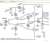
OK, so I don't like single supplies, but if you do then you do. I have no argument a'tall with the circuits you posted. I especially like Simple Stereo Electret Mic Preamp because he draws a nice schematic, i.e. you can make some sense out of the thing. However, it does have a maximum gain of about 20, which might not (or might) be enough.
<< I haven't seen to 2 battery in a NE5532 circuit before >>
Then good thing you ran into me. Whenever you see a power supply you can just as well think of it as a battery, and vice versa.
But that hookup is not for the single-supply circuit you want. But wait...do you know about single and dual supplies? Now I'm thinking not.
Single supply = a single, positive, power supply voltage to the circuit. The hookup is positive voltage to pin 8, ground to pin 4.
Dual/Split supply = two power supply voltages to the circuit, one positive and one negative. The hookup is positive voltage to pin 8, negative voltage to pin 4. Additionally there is a zero-volts ground which never connects to the NE5532 at all, but is circuit ground.
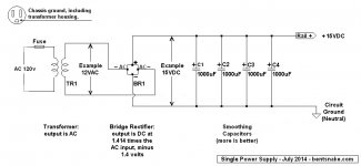
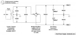
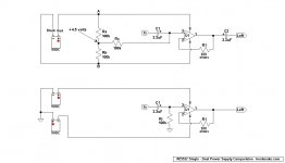
Just in case I'm posting an illustrative circuit for each kind of supply.
Totally unrelated to you is the fact that some on this forum go into a rant whenever they see these circuits. Those should know that they're looking at a close adaptation from Douglas Self's, "Self on Audio," so they should send their complaints and corrections to him.
.
Congratulations! Much happiness, and may there be many well-behaved bambinos & bambinas if you so choose, or otherwise not.
<< As this looks, isn't the power only going to the NE5532 and not the capsule >>
Yes. The circuits you posted have a power takoff for the mic capsule, while in the circuits we were discussing the mic capsule had its own battery. But either way is fine, six of one.
OK, so I don't like single supplies, but if you do then you do. I have no argument a'tall with the circuits you posted. I especially like Simple Stereo Electret Mic Preamp because he draws a nice schematic, i.e. you can make some sense out of the thing. However, it does have a maximum gain of about 20, which might not (or might) be enough.
<< I haven't seen to 2 battery in a NE5532 circuit before >>
Then good thing you ran into me. Whenever you see a power supply you can just as well think of it as a battery, and vice versa.
But that hookup is not for the single-supply circuit you want. But wait...do you know about single and dual supplies? Now I'm thinking not.
Single supply = a single, positive, power supply voltage to the circuit. The hookup is positive voltage to pin 8, ground to pin 4.
Dual/Split supply = two power supply voltages to the circuit, one positive and one negative. The hookup is positive voltage to pin 8, negative voltage to pin 4. Additionally there is a zero-volts ground which never connects to the NE5532 at all, but is circuit ground.
Just in case I'm posting an illustrative circuit for each kind of supply.
Totally unrelated to you is the fact that some on this forum go into a rant whenever they see these circuits. Those should know that they're looking at a close adaptation from Douglas Self's, "Self on Audio," so they should send their complaints and corrections to him.
.
Attachments
Last edited:
Thanks for the good wishes, we really appreciate it! I have a 25y/o and a 9 y/o (with autism), so my breeding days are over, but my kids love her almost as much as I do, so it is all good!
You are absolutely correct in your observation re power supplies, I am just starting to put together an understanding of implementations I have seen (hence the examples I posted), so having your clear tutorial is very much appreciated. I have to run at the moment, but will be giving it a thorough look later, thanks!
You are absolutely correct in your observation re power supplies, I am just starting to put together an understanding of implementations I have seen (hence the examples I posted), so having your clear tutorial is very much appreciated. I have to run at the moment, but will be giving it a thorough look later, thanks!
.
<< I am just starting to put together an understanding [of circuits]... >>
You walk where fiancees seldom should, and grooms never. There's a learning curve. By far the easiest way to understand this stuff is just go get a degree from MIT. That will be much faster and cheaper, leaving more time and money for the gang.
Ah well, as long as you remember the two rules that are the universal solvent.
1. She's right.
2. Make sure of it.
Moving along, I'll give you a an introductory lecture.
"Volts" is force, it's push (or pull, just as well). Voltage is what makes amperage flow. The correct name for volts is "Electromotive Force," which is why its symbol is E.
"Amperage" is a physical quantity (as far as we're concerned), it's what moves through a circuit (pushed by volts) and does work. The correct symbol for amperage is I, possibly for "intensity of current," possibly not (historians debate).
Any wall socket in your house has available a fixed voltage of 110 volts (220 in some countries), and any amount of current from zero until a breaker trips.
"Resistance" means resistance to amperage flow when voltage is present. Everything has more or less resistance, but usually you're talking about...resistors. Resistance might be referenced individually or collectively, that is, one component or an entire circuit. Its symbol is R.
Note: "Impedance" (symbolized by Z) is the AC version of resistance. We give it a different name because with capacitors impedance varies with frequency, while resistors stay the same. Impedance is of lesser interest to non-engineers except at an input (the input circuit), and an output (the speakers).
The interaction between E, I, and R is expressed by Ohm's law, which rules all. E = IR, which transposes to R= E/I, and I = E/R. Yes, it can just as well be E = IZ, but I advise ignoring that.
Moving along from there, all op amps are designed to run on a dual power supply, that is, a plus and minus voltage, with a center-point ground. This is not a law of nature, it's just how they're designed and intended to be used.
However, they can be made to work by creating a "virtual ground" circuit. We usually think of ground as being...ground, the earth, and usually it is. But actually "ground" is an arbitrary, it's just what we agree on as the zero-voltage point. So we can call anything ground and just measure everything from there. As with a virtual ground circuit.
I've posted the same circuit powered two different ways. In the top (single supply) circuit the indicated +4.5 volt point has become ground, the zero-volt point. Just because we say so, we created a virtual ground.
So put one lead of your voltmeter at the +4.5 volt virtual ground, which we re-define as zero volts. Measure to point A and you'll see +4.5 volts. Measure to point B and you'll see -4.5 volts. The op amp sees a plus and minus voltage supply, so it works. Only that the circuit is more complicated, to create that virtual ground. And by the way, most op amps of interest to you are not really designed for +/-4.5 volts, most are much happier working up around +/-15 volts.
BUT note well C1 and C2. Both are needed to isolate that +4.5 volt ground, because previous and following circuits probably have the expected "ground" ground.
Ummm...remember how I mentioned MIT?
===
GENERAL NOTE. Yes I've left out some components, notably smoothing, bypass, and decoupling capacitors. And yes C2 in the single-supply circuit, and C1-Ri in the dual-supply circuit, are unexpected values. None of which is, for crying out loud, germane to this discussion. The idea here is to give useful information, which means K.I.S.S.
.
Attachments
Last edited:
- Status
- Not open for further replies.
- Home
- Amplifiers
- Chip Amps
- input load/mic impedance