Here is a data sheet on one of the mics I will be testing
https://www.flickr.com/photos/9153447@N08/14663013701/
https://www.flickr.com/photos/9153447@N08/14663015131/
https://www.flickr.com/photos/9153447@N08/14663013701/
https://www.flickr.com/photos/9153447@N08/14663015131/
.
<< let me clarify...make a close mic on an instrument of that sort and make it sound real (natural) the way the player hears it acoustically...The problem is how to avoid feedback and other signals and get a sound with some space around it...This is impossible in the circumstance I mentioned >>
Clarification not needed, I'm familiar (not expert) with the environment you speak of, working on both sides of the footlights.
My turn to clarify. You seem to be speaking of more than just micing one cello, yes? I say yay, power to you. But you know you're sailing into waters that are not well charted. You have some learning curves to navigate, with the usual gnashing of teeth and cries of "why won't the damned thing work, where am I supposed to click?!" Of course it's always knowing where to click.
I very strongly recommend Audacity audio editor, a freebee and something of a world standard. Here's a link, or Google for "Audacity" and it will be near the top of of the results. The correct link is the one for sourceforge. ( Audacity: Free Audio Editor and Recorder )
As a for-instance, when you close-mic a horn what you get is...a horn. Space (reverb) is added in the control room. Movie guys say "they'll fix it in post," which by the way drives the guys in post-production crazy.
Moving along from there, you had the right idea in the first place, with your original post. You asked, "How can you modify the input impedance of a mic preamp circuit?"
Well, post #16 is how. In the "Electret Mic with Mic Amp" circuit change R1 to any value, and that's the input impedance of the circuit. If this seems too simple to work, well, that's why we use those little black chips. The engineers already did the math for us.
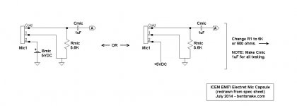
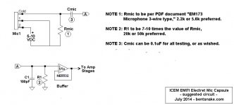
But testing is rarely simple. I've re-posted the microphone spec sheets you posted before. I've also posted a schematic that matches this capsule to the schematic in post #16.
Circuit note: The spec sheet states that the mic impedance is 600 ohms. This implies, but does not state, that impedance matching is required. So should the input impedance of the following stage be a matching 600 ohms, or a "times ten" 5K? I dunno. Either have to ask the manufacturer, or experiment. Asking is usually easier and cheaper. (It's expected that the internal circuitry of the capsule interacts with the specified 5.6K resistor to give a total output impedance of 600 ohms for the capsule.)
If you ask, be sure to find out how close you have to be to the stated 5 volts. With batteries you can get 4.5 or 6 volts, and I expect either would be fine, but better to ask.
The stated 600 ohm impedance implies an expectation of the "balanced line" that sreten spoke of so long ago. As an item of information, a balanced line has nothing to do with audio directly. Its purpose is to reduce noise picked up by connecting cables, and only that. So balanced lines can be ignored for testing.
This post has wandered quite a bit. But then, you didn't ask a question. Still, I thought this information might be both apropos and useful.
.
<< let me clarify...make a close mic on an instrument of that sort and make it sound real (natural) the way the player hears it acoustically...The problem is how to avoid feedback and other signals and get a sound with some space around it...This is impossible in the circumstance I mentioned >>
Clarification not needed, I'm familiar (not expert) with the environment you speak of, working on both sides of the footlights.
My turn to clarify. You seem to be speaking of more than just micing one cello, yes? I say yay, power to you. But you know you're sailing into waters that are not well charted. You have some learning curves to navigate, with the usual gnashing of teeth and cries of "why won't the damned thing work, where am I supposed to click?!" Of course it's always knowing where to click.
I very strongly recommend Audacity audio editor, a freebee and something of a world standard. Here's a link, or Google for "Audacity" and it will be near the top of of the results. The correct link is the one for sourceforge. ( Audacity: Free Audio Editor and Recorder )
As a for-instance, when you close-mic a horn what you get is...a horn. Space (reverb) is added in the control room. Movie guys say "they'll fix it in post," which by the way drives the guys in post-production crazy.
Moving along from there, you had the right idea in the first place, with your original post. You asked, "How can you modify the input impedance of a mic preamp circuit?"
Well, post #16 is how. In the "Electret Mic with Mic Amp" circuit change R1 to any value, and that's the input impedance of the circuit. If this seems too simple to work, well, that's why we use those little black chips. The engineers already did the math for us.
But testing is rarely simple. I've re-posted the microphone spec sheets you posted before. I've also posted a schematic that matches this capsule to the schematic in post #16.
Circuit note: The spec sheet states that the mic impedance is 600 ohms. This implies, but does not state, that impedance matching is required. So should the input impedance of the following stage be a matching 600 ohms, or a "times ten" 5K? I dunno. Either have to ask the manufacturer, or experiment. Asking is usually easier and cheaper. (It's expected that the internal circuitry of the capsule interacts with the specified 5.6K resistor to give a total output impedance of 600 ohms for the capsule.)
If you ask, be sure to find out how close you have to be to the stated 5 volts. With batteries you can get 4.5 or 6 volts, and I expect either would be fine, but better to ask.
The stated 600 ohm impedance implies an expectation of the "balanced line" that sreten spoke of so long ago. As an item of information, a balanced line has nothing to do with audio directly. Its purpose is to reduce noise picked up by connecting cables, and only that. So balanced lines can be ignored for testing.
This post has wandered quite a bit. But then, you didn't ask a question. Still, I thought this information might be both apropos and useful.
.
Attachments
the post22 mic already has a pre-amp built in.
That preamp requires a receiver load of 5k6.
You simply provide sufficient gain in the receiver amp to give the output level you need.
That preamp requires a receiver load of 5k6.
You simply provide sufficient gain in the receiver amp to give the output level you need.
I apologize that this has wandered a bit, but it has most illuminatingly answered my question as to the mechanism in this sort of circuit that effects the load placed upon the input. As my interest extends to 2 very different types of input devices, a bit of a wander has produced what for me is an incredibly useful discussion. I really appreciate the effort and patience that brought it to this place. Thanks!
Last edited:
.
AndrewT:
Thanks for the information, but I wish your post hadn't been so brief. Please let me see if I understand.
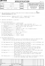
If I understand the data sheet you reference (which I might not), the stated sensitivity of this capsule is "-45 dB +/- 3dB at 1kHz," and this translate into a voltage ouput of approximately 5 milivolts (0.005 volts) at 1kHz.
And by a 5.6K receiver load you mean matching (balanced) impedance, not the "output impedance times 10" rule of thumb? I'd like very much to learn what on the data sheet tells you this?
Am I getting this at all?
.
AndrewT:
Thanks for the information, but I wish your post hadn't been so brief. Please let me see if I understand.
If I understand the data sheet you reference (which I might not), the stated sensitivity of this capsule is "-45 dB +/- 3dB at 1kHz," and this translate into a voltage ouput of approximately 5 milivolts (0.005 volts) at 1kHz.
And by a 5.6K receiver load you mean matching (balanced) impedance, not the "output impedance times 10" rule of thumb? I'd like very much to learn what on the data sheet tells you this?
Am I getting this at all?
.
.
nycellist:
I know you'll be stunned to find out that I don't know everything. But hey, such is life.
One indication of my non-omnipotence is that I didn't study the data sheet you posted. If I had I'd have seen the electrical specs plainly stated: this capsule is speced from 3 to 10 volts approximately, so a 3 volt battery pack would work fine.
Otherwise, I'm not certain of AndrewT's meaning, so I hope he responds. But in any case I'm delighted to be able to give a little help.
.
Or a 9V? 🙂 One thing I've learned in life, is that there is always something for me to learn, and my ex-wives and children can confirm this...
I thank one and all for their input here, this is most illuminating
I thank one and all for their input here, this is most illuminating
Hi,
This may be an obvious question, but I have not been able to find the answer to this. How can you modify the input impedance of a mic preamp circuit? I have searched in as many ways as I could think of, and found no specific answer. As I understand it, the input load should be 10x the impedance of the mic for optimum performance. I would like to build a preamp based on the NE5532, and I am going to experiment with a variety of capsules with very different impedances (680-2200ohm) as well as a piezo film, which ideally requires a 10Mohm load. What part of the circuit determines the load?
Thanks for your patience with my query!
To the best of my knowledge, most normal microphones only need the load impedance to be greater than or equal to 10 times their own impedance. There is no optimum, it just needs to be large enough.
To get decent noise performance over a huge range of source impedances, I'd go for a FET input stage. For example, take an OPA132 and make a noninverting amplifier with it, using a resistor of no more than a few hundred ohms between its inverting input and ground. The resistance needed between output and negative input depends on what gain you want. If the required gain is high, say more than 100, or if you want low-frequency roll-off, connect a capacitor in series with the resistor between negative input and ground.
Connect a bias resistor between the positive input and ground that is big enough for your piezo transducer.
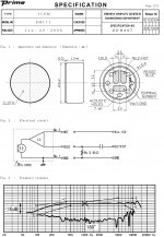
page 2/3 shows the circuit connection.
It has Hot into pin No. 2
Cold going into the unlabeled Pin
GND going into Pin No. 1
Hot = Vcc = +5V
Cold = the output line but must include the two components shown.
GND is the common between power supply and signal.
The suggested load is 5k6. This is also stated in line 3) of the electrical specification, They call it Rs (why?)
line 7) also confirms the 5V for Vcc but gives a tolerance range. This range may be absolute maximum rather than a recommended range of working Vcc.
Back to page 2/3
the mic shows an IC.
This IC has 4 connections. I suspect this is an amplifier as well as a power supply to the electret condenser. I can't see any reference to piezo.
The output is not balanced impedance.
I am a mic newbie.
Don't take anything I say as gospel, get corroboration, either from others, or the datasheet.
Last edited:
.
AndrewT:
Thanks for your reply. I simply didn't notice the electrical specification, possibly due to not looking. The squiggly line is the mathematical symbol for "approximately," so supply voltage is speced as approximately 3-10 volts--including, as nycellist said, 9V.
Moving along to my personal problems, all electret capsules use a preamp housed inside the capsule.
Wikipedia: Electret microphone - Wikipedia, the free encyclopedia
Panasonic: http://industrial.panasonic.com/www-data/pdf/ABA5000/ABA5000PE44.pdf
My [latest] confusion comes from the ICEM-EM171 data sheet, page 1, line 4-3, the symbol Rs.
"Vs" in schematics means "voltage: signal," i.e. the incoming audio signal voltage. (N.B. Vs does NOT mean "volts: supply," as in power supply voltage.)
So if Vs means "voltage: signal, I took "Rs" to mean "resistance: signal," translating that to mean the impedance of the device, the "device" being the mic capsule complete with battery, resistor, and capacitor. Read this way, the output impedance of the capsule complete is 5.6K.
But while line 4-3 gives an "Rs" value of 5.6K, at the same time in the same line it states that impedance is 600 ohms. The upshot is that I don't know what to think, and I wish these people would make up their minds.
I can only restate my long-held and very strong opinion that engineers should not be allowed to write technical documents. If you want engineering done, then sure, hire an engineer. But it you want writing done, for crying out loud hire a writer.
.
Last edited:
You have this back to front..................I can only restate my long-held and very strong opinion that engineers should not be allowed to write technical documents. If you want engineering done, then sure, hire an engineer. But it you want writing done, for crying out loud hire a writer.
.
It is engineers that should be hired to write the technical documents.
Only non engineers to edit them and submit back to the engineer for approval.
It's non engineering writers that cause the confusion by using terms they don't understand !
Rs is usually reserved for source resistance, i.e. the resistance seen by the load looking back at the source connection.
The 600ohm could be the output impedance of the amplifier inside the capsule.
The 5k6 looks like the recommended load for that amplifier.
If you add on an external amplifier it will look back and see the output capacitor and then 600ohm||5k6 resistor.
I would expect that the capsule amplifier would not like to see a load significantly lower than the 5k6, unfortunately the spec does not tell us.
I suggest an input impedance/resistance (Rin) of around 20k for your amplifier. But that is just a guess.
It is this external amplifier that should be designed to drive your connection cable and to bring in the 5V for the PSU.
The output of the external amplifier can be unbalanced or balanced.
It can have the ability to drive a few tens of pF, for short cabling, or a few thousand pF for much longer cabling.
Last edited:
It is true that some engineers can't write. My experience is that some can write, and some writers can't write. I once worked on a project where one of my tasks was to check the work (for technical accuracy) of the technical author we had hired. Both he and I were surprised when I returned his drafts covered in red ink, most of which was due to poor English rather than poor grasp of technicalities. My conclusion was that if you want something written then hire a literate engineer, not a writer.bentsnake said:I can only restate my long-held and very strong opinion that engineers should not be allowed to write technical documents. If you want engineering done, then sure, hire an engineer. But it you want writing done, for crying out loud hire a writer.
.
<< The 600ohm could be the output impedance of the amplifier inside the capsule...The 5k6 looks like the recommended load for that amplifier >>
My point exactly. It could be, and it looks like. So I'll put together an input circuit that could be 600 ohms, although it looks like 5.6k. Now then...where to get parts that could be, and they also have to look like.
<< ...an input impedance/resistance (Rin) of around 20k... >>
By far the wisest course, in my view. Grumpgrump.
.
Last edited:
You need to follow the circuit given by the manufacturer.
You need the 5k6 and the capacitor.
You need that coupling circuit.
It's the way to get power in and a signal out of the mic.
After that you add your external amplifier.
You need the 5k6 and the capacitor.
You need that coupling circuit.
It's the way to get power in and a signal out of the mic.
After that you add your external amplifier.
I have written to the distributor for clarification. All of their data sheets for the mics I am working with are the same, in this regard. In looking at it again, it seems that this is the suggestion for the input to the amplifier circuit.
I just heard back from the distributor. On a sideline, these docs are originally written by Japanese engineers, so there is another layer of complexity.
The document refers to an omni capsule, but I am told everything under discussion here is the same as this.
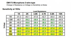
Interesting data
The document refers to an omni capsule, but I am told everything under discussion here is the same as this.
Interesting data
Attachments
Remembering that I am a mic newbie, it looks to me that the mic capsule can accept a very wide range of Vcc from 1V to 10V. Is that correct?
The low load values of 1k and a bit over suit low SPL
the high load values of 5k6 & 10k suit high SPL
is that correct?
High SPL will require higher Vcc
Very low SPL could usefully use the lower Vcc & Lower load values since noise and s/n ratio are better.
Is that correct?
The low load values of 1k and a bit over suit low SPL
the high load values of 5k6 & 10k suit high SPL
is that correct?
High SPL will require higher Vcc
Very low SPL could usefully use the lower Vcc & Lower load values since noise and s/n ratio are better.
Is that correct?
.
So that's how you find stuff out. Ask somebody. Whatta concept.
Speaking of power applied to the capsule-resistor-capacitor combination, the new graphs answer all questions. From 5 to 10 volts, inclusive, does the job. Comparing the graphs to the charts confirms this, there's no difference I'd call significant. I've posted one chart with highlighted values just as a for-instance.
The impedance situation is still not as brilliantly clear as I personally would like. But in my mind the critical fact is that nobody says anything about impedance matching, which puts the whole shebang squarely into the "output impedance times ten" category.
By the way, we're somewhat into the nitty gritty here, so I'm going to mention that the "times 10" rule is actually "from 7 to 10 times." This complements the fact that electronic values are never exact to begin with. This means you don't design on the edge unless you're NASA, everybody else designs in the middle of a range.
Getting back, I look at the new charts in combination with Panasonic's notes regarding ECM (Electret Condenser Microphone) capsules, which I've also posted. I take into account the fact that these capsules are usually designed for use in a vast array of devices, very seldom do you run into a single-purpose ECM capsule.
The upshot is my conviction that, in a word, it don't matter. This capsule can be used like any other.
For 20-20k Hz audio purposes, the resistor in the capsule-resistor-capacitor combination can be chosen from the chart, or at random. The most common value I know of for this resistor is 2.2k, practically the whole world uses it. This would call for R1 in the schematic I've posted to be 20k.
However, the capsule's data sheet calls for a 5.6k resistor, making R1 50k, so...why not? Sure.
Except...did you really think it would be that simple? C'mon.
Resistors are subject to "Johnson noise." This is the sound of current flowing, the molecules in the resistor getting stirred around, it's heard as a faint hiss. No kidding, this is real.
The higher the resistance, the greater the Johnson noise. This is why the rule with little black chips is to keep resistor values as low as possible. In the tenish-twentyish k region is preferred.
50k is getting up into the Johnson noise region, kinda, more or less. So if you use a 5.6k/50k resistor combination, and you hear a faint hiss you can't live with, then suspect Johnson noise, and go to the 2.2/20k combination.
I don't know why they make these things so complicated. I've complained, but so far nobody has done anything.
We understand that all of this is my best judgment, which translates into my best guess. If anybody has a better thought I'm wide open.
.
Attachments
Last edited:
except that I prefer >20times if the impedances can be selected to achieve that.By the way, we're somewhat into the nitty gritty here, so I'm going to mention that the "times 10" rule is actually "from 7 to 10 times."
50k Rin would suit <2k5 Rs. I can do a lot better than that.
But if I had a 100r Rs feeding a first stage attenuator of 2k I could just achieve 20times.
If the output of that first stage attenuator never exceeds 525r then the second stage must be >= 10k5.
I could use 10k.
The maximum output impedance is 2k6 and that would feed Rin = 52k.
It is just about possible to use passive attenuators in two stages between Rs=100r and Rin=50k without needing buffers to get to that 20times target.
The aikido attenuator is a two stage attenuator that uses three switches to give 1.5dB volume adjustment from -54dB to 0dB AND gives stereo balance control.
BUT !!! the designer forgot about the interstage impedances and the control function/slope falls apart due to using the wrong resistor values.
Changing the resistor values of the first stage cured the error and makes a very good stepped stereo balancing and vol pot in a cheap package.
Your mic to receiver needs similar assessment.
What can the mic drive?
How loud/quiet can it go?
What gain is required in the receiver?
How much noise can it tolerate?
Does any part need long cables?
Does any part need balanced impedance connections to minimise interference?
All these are interlinked
yes, if that is the source impedance seen by the stage.50k is getting up into the Johnson noise region,
Your mic is NOT that.
The 50k is parallel to the 5k6. That reduces the source impedance seen by the amplifier to 5k
In the passband the capacitor passes signal. In the passband the mic internal amplifier has an output impedance of 600ohms.
That 600ohms is parallel to the 5k calculated earlier.
The effective source impedance in the passband is 5k//600ohms = ~540ohms
The input noise that the external amplifier adds on to it's own noise is that created by 540r, in the passband. The LF noise (because the capacitor blocks the LF signal) will be based on the 5k. Will this matter?
Then choose the capacitor to get the best compromise between LF noise and width of LF passband.
- Status
- Not open for further replies.
- Home
- Amplifiers
- Chip Amps
- input load/mic impedance