Eh, there must remain something that essential for the next iteration.It just needs some green LEDs..

that would be Babelfishing Babelfished Babelfish

Tombo - are you old enough to remember na ratluku nacrtana devojka koja u ruci drzi ratluk na kojem je nacrtana devojka koja u ruci drzi ratluk na kojem je nacrtana devojka koja u ruci drzi ratluk na kojem je nacrtana devojka koja u ruci drzi ratluk na kojem je nacrtana devojka koja u ruci drzi ratluk na kojem je .......
well, there is no available smiley to show level of hysterical laugh now .........
I’m more than old enough but can’t remember that specific one. Though description is enough to laugh as mad.
well I did kill my self, spending entire afternoon searching for picture of exact one ...... none, nada, zilch
internet is simply POS, if there is no picture of that
one of most hilarious things from collective inheritance
internet is simply POS, if there is no picture of that
one of most hilarious things from collective inheritance
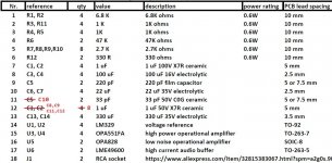
BOM is attached as excel file and as Mouser shared basket. There are some odd values and unnecessary tight tolerances, but they are result of parts availability.
Mouser shared basket
C3 & C4 can be any decent electrolytic capacitors for 16 V or more. High quality low leakage types are preferred.
C6 & C7 again nothing critical except 25V or more.
C13 & C14 could be any low ESR 220-330 uF capacitors with 25V or higher rating. Though, I prefer hybrid polymer capacitors for supply lines as they combine best of both worlds: low leakage, low ESR, long life, high ripple capacity.
Ceramic capacitor can be used for C5 on condition that it is C0G type. Film type is preferred.
RCA socket can be purchased from this (highly recommended) seller: RCA sockets
That one is intended for placement as on first picture. But pins can be straightened and it can be used mounted at 90 degrees angle. I did just that. Soldered with only 2 pins it is little wobbly, but that is cured by little hot glue at its sides (not visible anyway).
Proper RCA type for 90 degrees placement can be found at Audiophonics site. It is several times more expensive.
Audiophonics
Attachments
Boards and parts ordered.
Thanks Tombo!
I'll have a couple extra pcb pairs if anyone is interested. USA only please in order to keep shipping el cheapo.
Thanks Tombo!
I'll have a couple extra pcb pairs if anyone is interested. USA only please in order to keep shipping el cheapo.
Changing buffer gain
Buffer gain is determined by usual voltage divider formula as 1 + R12/R11.
In example, with BOM values gain will be 1.33 x (1 + 330/1000). For 2x gain R12 should be 1000 Ω.
Input impedance can be changed with R6 and 100 KΩ is OK as well.
Buffer gain is determined by usual voltage divider formula as 1 + R12/R11.
In example, with BOM values gain will be 1.33 x (1 + 330/1000). For 2x gain R12 should be 1000 Ω.
Input impedance can be changed with R6 and 100 KΩ is OK as well.
Thank you tombo for this project idea and the effort and thought you've put into it. Looks really well done and easy to implement. It looks like you've covered all the bases here and has me re-thinking my plan with my gainstage. I guess maybe I should try and finish my rebuild already in process, and build your input buffer with some gain as an alternate and see what I like.
Yes, you are right. Thanks for noticing.In the BOM, some C's are duplicates.
Are my changes correct?
After rows copy-paste I missed to correct some fields. Correct BOM is attached and added to the first post as complete project and separate files.
Correct required number of 1 uF/50V capacitors is 8. Though, on standard FW voltages, all 1 uF capacitors can be the same 1uF/50V, so 12 pcs. covers all. Power supply input capacitors are specified as 100 V because buffer can be supplied from +- 60V source.
Those fast on trigger, if not ordering 10 capacitors (lower price level by quantity) will have to make additional order. I’m sorry for that.
Corrected Mouser shared basket
Attachments
Ya I kind of learned the hard way over time, when needing 4,6,8..... just buy 10 to get the price break.
No problem with leaving R12 at proposed value (330 Ω) and change R11. Using 330 Ω for both R11 & R12 will provide 6 dB gain or 2x. LME49600 is very powerful and can drive low impedance loads. R11 & R12 also appear as load on output. Any reasonable combination of R11 & R12 can be used.
No reason to go with combined serial resistance of both resistors over several K or to go below several hundred Ω. All “lab” test were made with 32 Ω load.
No reason to go with combined serial resistance of both resistors over several K or to go below several hundred Ω. All “lab” test were made with 32 Ω load.
Last edited:
Thank you Tombo! 🙂
You are welcome, literally, as this was your first post on this great forum. 🙂
Here, in the Pass Labs forum section, you will be in very good company.
bunch of Weaklingsssessss

Yes, they don’t know how to resist new shiny toys.
- Home
- Amplifiers
- Pass Labs
- Input buffer for LuDEF, SissySIT and similar amplifiers