It is Onsemi 7805 (the classic TO220 version) I mentioned. Measured these years ago so real life/reality and they were lowest in noise. Kept a few in case I needed a low noise 5V. There are various other modern regulators that can be used with better specs. MCP1793 is simply darn noisy.
https://www.farnell.com/datasheets/3743668.pdf
All assumptions aside, because of your remarks I tested yesterday evening again how loud the Sabaj A10a can go and it was absolutely way too loud but still undistorted. Maybe MA12070 Watts are not the same as tube amp Watts 😀 (I can not help to chuckle while writing this). I don't know what theoretical analyssumption says about that but it is more than enough for me. The neighbors were outside and looked a little surprised. The setup was highly complex: audio player - testDAC - Sabaj A10a - loudspeakers. I will retest this evening with a simplified setup: audio player - Sabaj A10a - loudspeakers.
So apparently my perception of reality and/or my way of understanding seems to be off. I wish you all good luck with the project.
Last edited:
My tube test was also not entirely fair, as the tube amp cannot be used with active DSP. I threw it in there just to demonstrate that even though a watt is very well-defined and 1W from any device is still 1W but a gain stage structure and the amp input design can (seem to) make the speaker behave differently. Usually when introducing a piece of pro audio gear (some good deals the past few years) into a consumer stack or vice versa.
I stopped using my tube amps as mains a few years ago due to a nasty habit of leaving them on 24/7 which made the power company really love me. Same with the VSSA. I would guess the EL84 amp has maybe 4-6 good watts of (under 1% distortion) power.
It sounds like you have some nice speakers and some considerate neighbors! Odd looks are way better than a knock at the door, though you can always use the excuse of "I'm sorry I did not hear the door"

Wahoo! Attenuators on the highs fixed my horny hissers.
I can actually hear the amp's noise floor on my speakers :/
I have to be within 6 inches, but it is there. That's 2x bal input on 1M resistors run to earth ground. BUT it's only 6 inches and only the high sensititivity horn. I never listen that close because the speakers are the size of my torso.
Proper gain staging to incorporate the DBX should go a long way to removing the final bit of noise above noise floor.
I'll detail my attenuators and amp mods tomorrow since it's midnight. Trying to mod a dual ESS DAC to provide 4+V output but waiting on the boards to arrive.
All nodes with SMD or THT testpoints.Compact yet there is room to breathe. Is that an array of test points up top?
Oh yeah, my promised pics.
- Take note that your cable mfg pre-destroyed some insulation within the plug, but you don;t have extra length to fix it.

- Start by hand twisting together a U-Pad which isn't as pretty as you really wanted it to be. I used .01% resistors because why not.

- Bend the leads back to make two little nubs to nestle into the neutrik connector pin cups. Tin the twisted leads.
-Tin the ground wrap because the stray copper strands pose a risk of shorting. This also prevents cable flex from transitioning into the connector and destroying the U-Pad but does make reassembly difficult.
- Double back the wire over the short solder pads because the neutrik connector narrows towards the back and preventing a short to ground is vital. The current flow will be low enough that the potential for field interference/damping is trivial.

- Heatshrink and reassemble
- Remember the MFG ruined the insulation, panic over proximity between signal leads, shell, etc. Conformal coat the broken areas with MG chemicals 419D

Anyway, that's how I reduced a lot of noise on the MA12070 because the input is super low. I need to re-EQ because the bass is now bloated. Perhaps others who have had issues with lack of bass (previously addressed by adding LC filters on output) can try measuring their output sources and correlating those to the input data on the datasheet.

SE input: Varies but usually ~.9Vpp MAX (.63Vrms)
BAL input: 1.8Vpp MAX (1.27Vrms)
Coincidentally, my consumer AVR can output about 5-5.5Vpp on the SE line outs before distortion gets visible. (this shot was with o-scope using 'dot' plotting instead of line so it appears to have more distortion than in reality. I was also holding the ground and probe on different TRS contacts with one hand while operating the scope with the other.
Even a bog-standard CD player outputting 2Vpp SE will be way too hot for the MA12070. The MA12070 will attempt to normalize the input level by setting a DC bias (offset V) on the input levels to achieve its desired Vpp, but that is just another process which can be avoided by properly padding/setting output. In my case, it significantly reduced noise on the most sensitive drivers. I needed to use pads because DSP. Source gain control seems paramount.
One other little note on the PA3S. The volume pots are AWFUL. At each position the channel diff was a few hundred Ohms (on a 5k pot which is a rather large percentage diff for a voltage divider).
@JPS64 I think this supports your original design for a lack of volume pot. A 32 or 40-bit hybrid digital control (as has been common in AVRs and CD players for the past 15 years) on the source would appear to be a superior method for gain staging this particular chip. Since the digital attenuation would happen in a 32+-bit domain, a full 24-bit signal is still achieved at the analog inputs without invoking a clamp on the internal offset bias functions of the chip.

- Take note that your cable mfg pre-destroyed some insulation within the plug, but you don;t have extra length to fix it.
- Start by hand twisting together a U-Pad which isn't as pretty as you really wanted it to be. I used .01% resistors because why not.
- Bend the leads back to make two little nubs to nestle into the neutrik connector pin cups. Tin the twisted leads.
-Tin the ground wrap because the stray copper strands pose a risk of shorting. This also prevents cable flex from transitioning into the connector and destroying the U-Pad but does make reassembly difficult.
- Double back the wire over the short solder pads because the neutrik connector narrows towards the back and preventing a short to ground is vital. The current flow will be low enough that the potential for field interference/damping is trivial.
- Heatshrink and reassemble
- Remember the MFG ruined the insulation, panic over proximity between signal leads, shell, etc. Conformal coat the broken areas with MG chemicals 419D
Anyway, that's how I reduced a lot of noise on the MA12070 because the input is super low. I need to re-EQ because the bass is now bloated. Perhaps others who have had issues with lack of bass (previously addressed by adding LC filters on output) can try measuring their output sources and correlating those to the input data on the datasheet.
SE input: Varies but usually ~.9Vpp MAX (.63Vrms)
BAL input: 1.8Vpp MAX (1.27Vrms)
Coincidentally, my consumer AVR can output about 5-5.5Vpp on the SE line outs before distortion gets visible. (this shot was with o-scope using 'dot' plotting instead of line so it appears to have more distortion than in reality. I was also holding the ground and probe on different TRS contacts with one hand while operating the scope with the other.
Even a bog-standard CD player outputting 2Vpp SE will be way too hot for the MA12070. The MA12070 will attempt to normalize the input level by setting a DC bias (offset V) on the input levels to achieve its desired Vpp, but that is just another process which can be avoided by properly padding/setting output. In my case, it significantly reduced noise on the most sensitive drivers. I needed to use pads because DSP. Source gain control seems paramount.
One other little note on the PA3S. The volume pots are AWFUL. At each position the channel diff was a few hundred Ohms (on a 5k pot which is a rather large percentage diff for a voltage divider).
@JPS64 I think this supports your original design for a lack of volume pot. A 32 or 40-bit hybrid digital control (as has been common in AVRs and CD players for the past 15 years) on the source would appear to be a superior method for gain staging this particular chip. Since the digital attenuation would happen in a 32+-bit domain, a full 24-bit signal is still achieved at the analog inputs without invoking a clamp on the internal offset bias functions of the chip.
Ah. A lot of the noise was due to Marantz AVR having no ground, using RCA -> XLR into the driverack, the driverack having chassis ground, and the chassis touching each other. I put the driverack on a cheater plug and the noise floor went to an inaudible level. CD's still have a slight hiss but only when my ear is literally inside the waveguide.
I kinda think this silicon might be suuuuuuuuuper forgiving with the right MCU inputs to get it into the proper mode. After experiencing these PA3s without interference, on very short cables to some speakers I now feel quite proud of..... Dang. Just... dang. There is no over-bloated bass. There's just the right amount. No noise (any more), and with the poorly matched volume pots gone, balance is perfect.
Now that I have them all sorted I am big fan of the MA12070. Shoot, I will even give props to the designer of the PA3S. They did quite a good job. I still have some criticisms, but I cannot say that they really sacrificed much. Apparently per Topping's PR guy on ASR, the PA3s, PA5, and LA90 were all designed by the same dude. the PA3s was just his "show us what you can do" first go.
I got a Topping PA3s yesterday, I'm using it for a compression driver above 1.6k, I guess it's less than 2 watts.
(because I don't want to use two of my Purifis for that, maybe in the future if a smaller one is available)
I very quickly compared the Topping PA3s to the Purifi in a Left / Right comparison on a Scanspeak 2-way, very very surprised, I didn't notice much difference, I need to test that more in details someday.
(because I don't want to use two of my Purifis for that, maybe in the future if a smaller one is available)
- Is it a good idea to run it at near zero load?
- are mods available for it? for example I don't need the potentiometer.
I very quickly compared the Topping PA3s to the Purifi in a Left / Right comparison on a Scanspeak 2-way, very very surprised, I didn't notice much difference, I need to test that more in details someday.
Entire 'Mods" I did to my PA3s':
- Bypass volume pot lazy way one one amp. Can still damage amp if the pot is turned all the way down which would short input and output to ground. One of my pots had 300+-Ohm diff between two channels on the same input at all positions.
- Recommend removal, however; the front faceplate is fastened to the case on the inside. Without a 7" 2-2.5mm hex key with long skinny shank, and without the volume pot on the board, you will have no way to attach the front bezel / front pushbutton.
I removed vol pot on one of my amps and tried some .01% 1k resistors between in and out for fun to see if it would help the no/floating-signal noise inherent to the MA12070. No difference. Just short it out and put some CA glue in the shaft so it cannot be turned below max. The solder mask is very thin and easily damaged.
Shorted:

Removed (note damaged solder mask on ground from using solder wick) and looooots of solder:

- Remove relays from signal chain. I only use balanced sources because behind my media cabinet is a mess of power and data cables.
Method one (better) is to to remove the relay and bridge the bal or unbal to output. Again, minor solder mask damage.

Method two was an attempt to remove a diode on the BJT they had placed to sink current to latch the relay coils, but this only partly worked because this particular diode only controls the BAL direction and I shorted the BAL points on the bottom of the board anyway because I was too lazy to find the SE side diode. It might be up by the OP1626 SE input but I didn't want to risk it.

If you want to keep BAL/Unbal source select, the Omron relays are fairly nice and may not hurt at all. Honestly I only removed the pots because they were not similar resistances per channel, and I only removed the relays because I do not want the amps to ever pop into unbal mode and my home keeps getting more and more RF-producing automation devices in the switch plates, sockets, etc. You could do literally none of this and still have a perfectly fine amp if the mode switching and potential slight channel imbalance does not bother you. It is a 5k potentiometer so a few hundred ohms at the upper end is not a ton, but kinda sucks bad if the volume pot ever goes to the lower half.
MA12070 wants only 1.8VPP balanced input. If you feed it some spicy signals, it will clamp them via DC offset circuitry built into the front end of the amp chip. DC detect/protect on the amp chip (speaker side) takes one full second to activate as per datasheet. This seem to be about 1000x longer than it takes to blow a CD/tweeter. I am not sure what the isolation between I/O is on the silicon, so my gut says just gain stage it properly and apply limiters at the source or attenuators on the cables if using BAL input. SE input will be shunted by the opamp either way, but ASR mesurements showed improved performance at the full input Vpp so my personal rec (expecially for sensitive CDs) will always be to drop that SNR as low as possible.

Tips for disassembly:
The PA3S is fastened at both ends. The rear has two screws on the edges which go through to the extruded chassis interior channels (which have been tapped). The front has two screws that fasten from inside (via reliefs in the internal extrusion channel) to the back of the front faceplate. You can either find a specialty 2mm ultra long >6.5"+) allen key or....
Remove the pot knob and retaining 10mm nut.
Opening guides/hints: https://www.audiosciencereview.com/...ubjective-impressions.7642/page-5#post-566069

This photo shows the front bezel securing method inside the case. The extrusion profile was milled away to allow the screw head to be captured. The remaining interior extrusion channel prevents all but the narrowest and longest of hex keys from accessing the fastener from the back side (after the rear screws are removed, and through the channel into which the rear screws fasten).

My heatsinks don't even get warm to the touch when mounted as topping provides (on top of the plastic MA12070 case). I may mill down the relief areas of the sink and the case bottom to see if they actually do anything when mounted to the bottom of the chip (designed to remove heat via epad) since the PCB itself does get warm in use.
- Bypass volume pot lazy way one one amp. Can still damage amp if the pot is turned all the way down which would short input and output to ground. One of my pots had 300+-Ohm diff between two channels on the same input at all positions.
- Recommend removal, however; the front faceplate is fastened to the case on the inside. Without a 7" 2-2.5mm hex key with long skinny shank, and without the volume pot on the board, you will have no way to attach the front bezel / front pushbutton.
I removed vol pot on one of my amps and tried some .01% 1k resistors between in and out for fun to see if it would help the no/floating-signal noise inherent to the MA12070. No difference. Just short it out and put some CA glue in the shaft so it cannot be turned below max. The solder mask is very thin and easily damaged.
Shorted:
Removed (note damaged solder mask on ground from using solder wick) and looooots of solder:
- Remove relays from signal chain. I only use balanced sources because behind my media cabinet is a mess of power and data cables.
Method one (better) is to to remove the relay and bridge the bal or unbal to output. Again, minor solder mask damage.
Method two was an attempt to remove a diode on the BJT they had placed to sink current to latch the relay coils, but this only partly worked because this particular diode only controls the BAL direction and I shorted the BAL points on the bottom of the board anyway because I was too lazy to find the SE side diode. It might be up by the OP1626 SE input but I didn't want to risk it.
If you want to keep BAL/Unbal source select, the Omron relays are fairly nice and may not hurt at all. Honestly I only removed the pots because they were not similar resistances per channel, and I only removed the relays because I do not want the amps to ever pop into unbal mode and my home keeps getting more and more RF-producing automation devices in the switch plates, sockets, etc. You could do literally none of this and still have a perfectly fine amp if the mode switching and potential slight channel imbalance does not bother you. It is a 5k potentiometer so a few hundred ohms at the upper end is not a ton, but kinda sucks bad if the volume pot ever goes to the lower half.
MA12070 wants only 1.8VPP balanced input. If you feed it some spicy signals, it will clamp them via DC offset circuitry built into the front end of the amp chip. DC detect/protect on the amp chip (speaker side) takes one full second to activate as per datasheet. This seem to be about 1000x longer than it takes to blow a CD/tweeter. I am not sure what the isolation between I/O is on the silicon, so my gut says just gain stage it properly and apply limiters at the source or attenuators on the cables if using BAL input. SE input will be shunted by the opamp either way, but ASR mesurements showed improved performance at the full input Vpp so my personal rec (expecially for sensitive CDs) will always be to drop that SNR as low as possible.
Tips for disassembly:
The PA3S is fastened at both ends. The rear has two screws on the edges which go through to the extruded chassis interior channels (which have been tapped). The front has two screws that fasten from inside (via reliefs in the internal extrusion channel) to the back of the front faceplate. You can either find a specialty 2mm ultra long >6.5"+) allen key or....
Remove the pot knob and retaining 10mm nut.
- Remove the back 2 securing screws
- Gently pull on the entire PCB assembly from the edges of the main board only
[*]Gently pull until you feel the front panel disconnect - Remove the front bezel with a long extension and 2mm allen key.
- Accept that the front will always be loose because you need to fasten the cable holding the front button and did not want to buy a $10-15 allen key just to please the stupid enclosure design
- Hold the bezel to the case with the pot nut.
Opening guides/hints: https://www.audiosciencereview.com/...ubjective-impressions.7642/page-5#post-566069
This photo shows the front bezel securing method inside the case. The extrusion profile was milled away to allow the screw head to be captured. The remaining interior extrusion channel prevents all but the narrowest and longest of hex keys from accessing the fastener from the back side (after the rear screws are removed, and through the channel into which the rear screws fasten).
My heatsinks don't even get warm to the touch when mounted as topping provides (on top of the plastic MA12070 case). I may mill down the relief areas of the sink and the case bottom to see if they actually do anything when mounted to the bottom of the chip (designed to remove heat via epad) since the PCB itself does get warm in use.
Attachments


Last edited:
Ma12070 diff. analog input "absolute maximum rating defined as follows.
Analog: IN0A, IN0B, IN1A, IN1B -0.5 to +6.0 V
1) Inputs are swing positive and negative voltage but so i do not understand the statement here above. Is it peak to peak? If so what is -0.5?
2) what can we do to protect inputs from over voltages. I found some circuits what do you think?
Analog: IN0A, IN0B, IN1A, IN1B -0.5 to +6.0 V
1) Inputs are swing positive and negative voltage but so i do not understand the statement here above. Is it peak to peak? If so what is -0.5?
2) what can we do to protect inputs from over voltages. I found some circuits what do you think?
Attachments
The analoge inputsignal is added to a Vref with is DC 1.5 to 2.5V at the inputs. So it is allowed to have - 0.5v to the Vref.
I have tested input clipping and MA12070 shuts down output immediately.
I have tested input clipping and MA12070 shuts down output immediately.
Why would anyone want to protect the inputs? What is the chance/risk of overvoltage in reality?
When stuff is built normally DC blocking caps are used and volume control is in the hands of the operator. The chip shuts off. I can imagine risks when having "open" power amplifiers connected directly balanced to balanced preamps without volume control in-between (so electronic volume control in the preamp or DAC). That is a disaster waiting to happen anyway. Any slight error will result in catastrophe.
You can take Sabaj A10a from your wishlist 🙂 It suddenly decided to die. The problem was in the volume control circuit that crackled and turning the volume knob resulted in the chip restarting and the display "booting". Of course I then opened it to see what went wrong. Ugly rework on the main PCB (shorted by sawing off a piece), no opamps only NJW1194. Not connected balanced internally. Sounded OK but there is better out there.
Last edited:
Well it happens to me i only have digital volume control. and playing with my dac output charge pump registers then suddenly i burned down the amplifier.Why would anyone want to protect the inputs? What is the chance/risk of overvoltage in reality?
When stuff is built normally DC blocking caps are used and volume control is in the hands of the operator. The chip shuts off. I can imagine risks when having "open" power amplifiers connected directly balanced to balanced preamps without volume control in-between (so electronic volume control in the preamp or DAC). That is a disaster waiting to happen anyway. Any slight error will result in catastrophe.
You can take Sabaj A10a from your wishlist 🙂 It suddenly decided to die. The problem was in the volume control circuit that crackled and turning the volume knob resulted in the chip restarting and the display "booting". Of course I then opened it to see what went wrong. Ugly rework on the main PCB (shorted by sawing off a piece), no opamps only NJW1194. Not connected balanced internally. Sounded OK but there is better out there.
Well there is also riisk for ESD.
Ma12070 diff. analog input "absolute maximum rating defined as follows.
Analog: IN0A, IN0B, IN1A, IN1B -0.5 to +6.0 V
1) Inputs are swing positive and negative voltage but so i do not understand the statement here above. Is it peak to peak? If so what is -0.5?
2) what can we do to protect inputs from over voltages. I found some circuits what do you think?
It's just saying you can have a 1.8Vpp input somewhere in the voltage range where the peaks and torughs do not exceed a certain positive or negative voltage above/below amplifier virtual ground. (-0.5 to +6V) before shutoff.
The line item above the audio signal level just means that the amp can 'deal with' an offset up to 3.8 V in the positive direction (4.8V Peaks with 3V troughs). Note that these are after the input capacitors. Specs are for the bare chip.
Examples:
All of these waveforms are okay because they do not exceed 1.8Vpp and they do not go above 6V and below -0.5V. If you exceed 1.8Vpp the chip will try to adjust the waveform offset which may distort or oscillate, even if it is in the acceptable range.
Gain staging with the MA12070 will give you the best results because even consumer gear can overdrive this chip. Note that consumer 0dBV reference is still 2.828Vpp and 0dBu level is still 2.19Vpp. My Marantz NR1711 will output ~5.4Vpp from the pre-outs before clipping. My STR-DN1060 will output ~4.6Vpp from Zone2 before clipping. My friend's STR-DN1070 will output the same. A to-spec CD player can easily output 2Vpp. Usually they go a touch higher to around 2x higher (4Vpp from a CD player is not uncommon). A decent phono preamp can go as high as 1.2Vpp depending on cartridge and gain. A cheap phono preamp can go higher.
At max, the MA12070 can take about -5dbV input. This might be a little annoying for people at first, but the closer you can get to the Vpp max of the MA12070, the greater the signal:noise ratio. You can always use a cheap RMS multimeter to measure between the center and surround on an RCA output then convert RMS to Vpp and set a volume limit.
This is safer and easier than trying to measure the amp outputs or volume pot pads to mark the volume potentiometer since most of these lower-cost amps have pretty poor pots, and the ground of your meter is likely very different than the amp ground (leading to potential speaker damage.... ask me how I know).
Here is a nice writeup on gain staging and noise floor for maximum dynamic range with systems using different levels. It is focused on mixing +4dBu and -10dBV systems, but since consumer gear follows standards very very loosely I believe it can help a lot of people.
https://www.hometheatershack.com/th...rom-pro-audio-equipment-in-your-system.35677/
The MA12070 is a good chip. But you have to play by its rules. Having a larger AC waveform (VPP) won't kill the chip (within limits) but exceeding the DC offset will let the magic smoke out.
Add a “fuse” so volume control in between. Always use coupling caps to the inputs as per datasheet. Solved.Well it happens to me i only have digital volume control. and playing with my dac output charge pump registers then suddenly i burned down the amplifier.
Well there is also riisk for ESD.
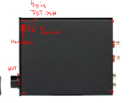
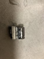
Today I modified an Aiyima A8. The first 2 opamps are only there for the analog outputs which I removed alltogether. Bass boost switch removed and 0 Ohm 0805 mounted instead. Fake/recycled/suspicious and also various types (HV and VZ) 1000/35 caps removed but for 1 and waiting for parts. Nice amplifier.
Last edited:
How did you verify these were fake?Fake 1000/35 caps removed but for 1 and waiting for parts. Nice amplifier.
Not verified but misprinted sleeves. I don’t trust them. They are already in the bin. Ah got them out for you.
Even if they would be original.. they’re different series and look used or recycled. Datecodes also all different.
Even if they would be original.. they’re different series and look used or recycled. Datecodes also all different.
Attachments
Last edited:
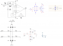
Anyway it seems the MA12070 is driven balanced in the A8 with volume control in the feedback loop but I’ll have to make a drawing to be sure. It has 3 dual opamps NE5532. That were 5 pieces originally. They are fed 12V via a switcher from the PVDD 26V.
A8 has different bass performance when compared to other Merus amplifiers.
A8 has different bass performance when compared to other Merus amplifiers.
Last edited:
For better or worse?A8 has different bass performance when compared to other Merus amplifiers.
- Home
- Amplifiers
- Class D
- Infineon MA12070 Class D