My cheap chineese board is based on MA12070P with I2S input, and noise from inductors is present above 10V power supply, no matter if music plays or not. When I replace inductors I will let you know if it solve the problem.
there might be a misconception here, my issue is resolved, it was caused by an open analogue input and not the output filter. I used the recommended filter configuration 3 (Infineon filter recommendations page 6) using quality components because I intended to use an PVDD above 15 V. I did not measure the output, but increased cable length and did get some audible noise above 5 m length, which is plenty for me.
have you seen new SMSL A100 ?
https://www.aliexpress.com/item/100...;114.38;-1;-1@salePrice;USD;search-mainSearchIt's only US $114.38 on alliexpress and you can even find it for ~90$ (shipment EU).
I am wondering if it could replace my BRZIHIFI TPA3255.
Probably this MA12070 will be not so powerful as amp with tpa3255 but in SMSL A100 there are two subwoofer out RCA, which might be quite cool (I always wanted to connect some subwoofer to my POLK Audio S15 speakers and to do it with tpa3255 I have to spend ~100$ for mini DSP)
Congratulations on getting your board working and dealing with the input noise issue.HI,
just a short update on my project:
I finally got my PCBs delivered and soldered the first board. I have bought the analogue and I2S versions of the chip and used the analogue version for my first test.
Having a reflow oven and a heat gun is great to get the job done, I don't think I could have it done without it.
Had to play around with the jumper for the correct setting but actually made no routing mistakes on the PCB, I'm super happy that it worked out that well 🙂
View attachment 1019408View attachment 1019409
The problem I have right now is the increasing noise when I supply the board with more than 10V... below 7 it's not really noticeable. Any suggestions for improvement?
Best Fabian
I've also just finished designing my board, and double and triple checking it for errors before sending the order in.
Your strategy for doing the analog version first makes sense, at least you don't need to deal with digital input set up issues. Noisy sound is at least sound, so confirms you are in the right direction. I was originally thinking of building the i2s version first, but now will do the analog one first.
I'm very confident with my though hole soldering skills, but have zero experience with SMD. In fact, I just bought my first tube of solder paste. 70:30 just to stick to something familiar. I've got a heat gun but no reflow oven. Really nervous with getting the MA12070 soldered right.
How did you apply solder paste, with a stencil or by hand? Also did the MA12070 self align easily when the solder melted as seen in many Youtube videos? I'm planning to use 70:30 tin/lead solder. Any advice in that?
Attachments
I have one, it works fine. I only use it for my tertiary setup though. I think abraxalito might have experience with this amp, but I could be wrong.Does anyone have experience with this very cheap amplifier with MA12070 chip?
https://www.aliexpress.com/item/100....store_pc_newArrival.8148356.3.3db93f299Iv6AA

Hi altus,
If you are new to SMD soldering, get some practice boards for learning, or order some cheap SMD 0Ohm resistors and some boards that are just chains of resistors.
The MA12070 was by far the hardest to solder I did so far. I used the T-962 reflow oven and it is a project on its own to make it useable... it's far from perfect, but when dialed in it is ok. There are good heat plates out there, and I think that it is easier to use one of those with a heat gun instead of an oven. I've heard that the SainSmart Miniware MH30 is very nice, and I might give it a try.
You definitely need a good soldering station/iron with a fine tip for fixing solder bridges between the pins of the MA12070 chip, there are some very good JBC clones if you are on a budget.
Last but not least, you need some kind of magnification for the inspection of the chip and removing bridges between pads. A stereo microscope is nice to have but cheaper camera microscopes will do the trick.
I used the CHIPQUICK SMDLTFP solder paste, it has a very low melting temperature and therefore is relatively easy to handle without the risk of damaging components. Don't forget to use flux 😉 Having a reliable multimeter with a temperature sensor helps get your profile correct when using your heatgun and/or hotplate, use some Kapton tape to fix it near your chip.
double-checking the board is crucial, and there is a big chance you miss some stuff anyway. I ordered the first batch from JLCPCB when I was sure that I had everything correct and noticed on arrival that I had grounded my VDD :|
...after rechecking I ordered a new batch of PCBs with a stencil. This makes it way easier to apply the correct amount of paste to the pads.
The most important thing I learned is to be patient and allow yourself to make mistakes 🙂
Best,
Fabian
Just bought this one out of curiousity and the general positive experiences with MA12070 when used with an opamp in front of the amplifier IC's. This ultra cheap amp even has those. Totally unexpected is that it has output filtering.
https://de.aliexpress.com/item/1005...1;23.53;-1;-1@salePrice;EUR;search-mainSearch
https://de.aliexpress.com/item/1005...1;23.53;-1;-1@salePrice;EUR;search-mainSearch
I thought about buying that amp too and will be interested in your opinion. The one thing that bothered me was they spec the max input voltage at 19V while the MA12070 can take up to 26V. Perhaps due to the small heatsink?
Could be the ratings of other parts just as well. It is a 24 Euro amplifier (shipping included) with fully closed casing so we shouldn't expect too much 😉 It will compete with a few FDA and my 2 x 3W class AB amplifier. As this is a switcherless home when audio is concerned it will be used with a regulated linear PSU.
To put things in perspective... the LT4320 based ideal rectifiers I use with audio stuff already cost twice the price of this complete amplifier.
With 15 ..19V real life output power will be around 2 x 20W. That is loud with normal loudspeakers.
To put things in perspective... the LT4320 based ideal rectifiers I use with audio stuff already cost twice the price of this complete amplifier.
With 15 ..19V real life output power will be around 2 x 20W. That is loud with normal loudspeakers.
Last edited:
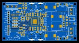
Here the internals of the $24 MA12070, taken from my friend's amp.
Looks like it has implemented a LC filter, but the 10uH inductors are more than what's recommended by Infineon. Also perhaps swap the 102 MLCC for a film cap for the LC filter.
Noise level was also a bit high, suspect the TL072 op amps are clones, but more challenging to swap as they are SMD


Looks like it has implemented a LC filter, but the 10uH inductors are more than what's recommended by Infineon. Also perhaps swap the 102 MLCC for a film cap for the LC filter.
Noise level was also a bit high, suspect the TL072 op amps are clones, but more challenging to swap as they are SMD
I wonder why the 1 µH coils have been removed and shorted?! Nice layout for that price but decoupling caps could have been closer to the IC. Wasn't a heatsink mounted?
Last edited:
On the reference board by Infineon, the only inductor on the +ve supply line is a ferrite bead configured as an CLC filter. From what I understand its more to prevent RFI leaking out. And that ferrite bead is nowhere near 1uh.
So I don't think the 1uh coil being shorted out will affect sound quality. I doesn't make sense for it to be there in the first place. 1uh is a very large value to be squeezed into such a small SMD footprint relative to the current demanded by the IC.
They probably got it wrong and realised it after making the PCB. Would be curious if the later amps have the same configuration replicated.
And no, there was no heatsink mounted.
It more looks like that a ferrite bead was planned/used just like on the reference board but simply got named "1 µH" on the board (the fact that the other beads at the board are called "10µH" supports that). There is a shortage of ferrite at the moment and some types have absurd long delivery times. The omitted one "1µH" has a larger footprint (1210?) and another value.
I think the designer went the extra mile compared to the minimum as presented in the datasheet. The paralleled decoupling caps show that. I have seen branded amplifiers with a worse layout than this cheapo.
I think the designer went the extra mile compared to the minimum as presented in the datasheet. The paralleled decoupling caps show that. I have seen branded amplifiers with a worse layout than this cheapo.
Last edited:
BTW that 3.5 mm connector switches the inputs apparently from RCA to 3.5 mm jack. That is easily changed.
Interesting I read in the spec that this chip supports single ended - capacitor coupled operation. Yes, amplifier current returned to GROUND no problemo - vs into the adjacent amplifier output. Hmmmm. 4 channels, 1000uf coupling gets down to 20Hz with 8 ohm speakers.
That's 4 discrete channels - if you can get the "front" data into the SD0 input and the "rear" into the SD1; that would be some kind of an I2S challenge.
Or, in ordinary stereo mode you could - clearly - drive 4 speakers, if one wanted to play with bipoles and dipoles - and didnt care as much for having the most power it can output. I suspect any of these "BD" modulated class Ds could do the same, but perhaps, only the Infineon....
Why would you want to change that?BTW that 3.5 mm connector switches the inputs apparently from RCA to 3.5 mm jack. That is easily changed.
Simple. I never use 3.5 mm connectors and secondly the switching (plated ferro?) contacts of such a cheap connector are not most reliable. At least that is my experience with cheap 3.5 mm connectors. RCA is way better for quality audio. Thirdly will plugging in a 3.5 mm connector while the device is switched on lead to nasty sounds. Comes with the nature of these connectors as they are meant for and used on portable stuff.
Last edited:
Fabian,Hi altus,
If you are new to SMD soldering, get some practice boards for learning, or order some cheap SMD 0Ohm resistors and some boards that are just chains of resistors.
The MA12070 was by far the hardest to solder I did so far. I used the T-962 reflow oven and it is a project on its own to make it useable... it's far from perfect, but when dialed in it is ok. There are good heat plates out there, and I think that it is easier to use one of those with a heat gun instead of an oven. I've heard that the SainSmart Miniware MH30 is very nice, and I might give it a try.
You definitely need a good soldering station/iron with a fine tip for fixing solder bridges between the pins of the MA12070 chip, there are some very good JBC clones if you are on a budget.
Last but not least, you need some kind of magnification for the inspection of the chip and removing bridges between pads. A stereo microscope is nice to have but cheaper camera microscopes will do the trick.
I used the CHIPQUICK SMDLTFP solder paste, it has a very low melting temperature and therefore is relatively easy to handle without the risk of damaging components. Don't forget to use flux 😉 Having a reliable multimeter with a temperature sensor helps get your profile correct when using your heatgun and/or hotplate, use some Kapton tape to fix it near your chip.
double-checking the board is crucial, and there is a big chance you miss some stuff anyway. I ordered the first batch from JLCPCB when I was sure that I had everything correct and noticed on arrival that I had grounded my VDD :|
...after rechecking I ordered a new batch of PCBs with a stencil. This makes it way easier to apply the correct amount of paste to the pads.
The most important thing I learned is to be patient and allow yourself to make mistakes 🙂
Best,
Fabian
Thanks for the tips. I guess its practice, practice, practice.
I'm waiting for my PTC heater to arrive, then build a simple Arduino based temp controller for it. Plan to set the heater plate to take the board to 'pre-heat' temperature, then hit it with the heat gun. I'm planning to put just enough heat on the board so the heat gun can ramp up temp quickly and melt the solder
I suppose the right pre-heat and heat gun temperature will be critical and will be determined after lots of test runs. Just as well I've got a few pieces of pre-ROHS junk boards to practice with, so they would mimic my tin-lead paste I'm using.
And yes, need to order some Kapton tape to attach my temperature sensor to the board to get a good feedback. Still thinking about low temperature solder and stencils.
Patrick
Those MA12070 amps from Aliexpress ebay etc looks like a sweet candidate for my computer speakers, my question is whether 15 V really is the lower limit and why, just wondering as the datasheets for that chip allows for as little as 4 Volts, and I was thinking of driving the amp from the 12 V PC supply.. is that possible?
If your amp only has the MA12070 chip, then it would work, but that is seldom the case. Most amps come with at least an opamp balanced input generator, a switching power supply to generate 5v and some kind of circuit to enable a click/popless turn on/off.Those MA12070 amps from Aliexpress ebay etc looks like a sweet candidate for my computer speakers, my question is whether 15 V really is the lower limit and why, just wondering as the datasheets for that chip allows for as little as 4 Volts, and I was thinking of driving the amp from the 12 V PC supply.. is that possible?
The input opamps and most good switching IC's should operate at 12v, but not 100% certain if the turn on/off circuit would still work.
If you are confident with tinkering around, most on/off control circuits are made out of discrete transistors, which enables some modification.
- Home
- Amplifiers
- Class D
- Infineon MA12070 Class D