You make sense, as always. 🙂AKSA said:I use 5A fuses on the power rails of the AKSA 55, and 7.5A on the AKSA 100. No one has ever complained of this minimalist arrangement, no one has commented on bass distortion, and no speaker or home has ever caught fire. If your circuit is Class A, then the standing current will be high anyway, and the current variation rather less than a Class AB circuit like the AKSA. This significantly reduces the thermal distortion. I suggest rail fuses are a good idea, inexpensive, safety oriented, and effective, without costing sonics at all.
However, the problem with fuses is that they react too slowly, and are too imprecise in their ratings. It is possible that with a blown OPS, you may be pumping current to the speaker for long enough to burn the coil, before the fuse blows. I'm not saying SOAR protection is the answer. All I'm suggesting is that we need to look for some other protection mechanism besides fuses to detect overcurrent on the supply rails and shut off the power supply. The only way I can think of doing this is by putting a precise 0.01 Ohm resistor in the rails, measuring the voltage drop across it using a comparator, and then triggering an SSR which controls the mains supply to the power transformer. That will in fact protect both the amp and the speaker, and will have no sonic effects at all. The drawbacks are in cost and complexity.
BTW, your countryman Rod seems to share your distrust for current limiting protection circuits in amps. 🙂
Thanks Hugh!
It is now clear that we should incorporate a fuse in power rails. AKSA has had good experience in this regard.
In another field mainly RF design were I do most of the work price to performance ratio is that I give more importance too.
Output devices Vs Drivers , anyday I will prefer sacrificing the output devices to drivers. Secondly I would not like to introduce more new circuitry into the existing JLH design that has been so painstakingly refined over the years.
Another point worth considering is that not all of us are equally confortable when it comes to designing, debugging and assembly of new circuitry so we should keep it simple. I Fuse in supply rail is good protection option and should be retained.
I am working on the new board layout I will be soon presenting it for your suggestions.
Regards
Rahul
Hi Tarun, Rahul,
Thanks for your posts; this is interesting, because the slightly different POV reflect the distinction between concept and reality. This is actually very educative, because it points out to all watching this thread how risk is balanced.
Tarun wrote:
You are right; fuses do react rather too slowly, but let's look at the figures.
According to Christer's figures, if we have a 2A fuse on the JLH, then with 2.1 times the current, namely 4.2amps, the typical response time to blow is from 50mS to 2 seconds.
With a nominal 8R driver (and with a crossover the rating might well be less than anyway, leading to higher DC currents if there is an 'accident') the voice coil is around 6.8R DCR. 4.2 amps DC will require around 28.5 volts, which as I understand it with the higher power JLH is about right. Of course, as the VC heats up the DC resistance will increase, reducing current, but we will stay conservative. This current represents a dissipation of IsquaredR, which is 120 watts continuous.
Let's assume that the speaker is rated at 50 watts continuous. On music, the actual heating value of 50W rms will be about half this, so clearly a dissipation of more than four times this will heat and destroy the voice coil rapidly. However, it will take a few seconds, and since the fuse is rated at just 2A, the fuse, rather than the voice coil, will blow before this time, with a good chance your driver will be OK.
If you use a speaker rated at even higher power, then there is a good chance the driver will suffer no damage. Of course, you might never actually blow the voice coil, just burn it, and if you do a good job of it, the multilayer VC might even pole against the magnet, causing soft scratching noises, indicating an expensive recoil is required.
Finally, consider a major cause of OP stage failure; cross conduction. This occurs in direct coupled amps when both outputs conduct together at high current from rail to rail during oscillation. This is more likely with a Class AB amp, but it might happen during clumsy bias setup of a JLH, though with little chance of oscillation.
Thus, there is always a chance you will destroy a speaker on a direct coupled SS Class A amplifier. But it is small once the amp is set up correctly and operated at sensible levels. If overloaded, and both output devices are destroyed, then the rail fuses will blow owing to excessive current, but this will happen so quickly the speakers will not be endangered. In twenty years of audio I have destroyed about three drivers (including one quite recently, dammit!), and all because of carelessness, not because of intrinsic deficiencies of design or implementation.
BTW, a fuse on the rail will not automatically create distortion in the speaker rail because the amplifier's negative feedback loop will automatically compensate for small variations in supply voltage.
Cheers,
Hugh
Thanks for your posts; this is interesting, because the slightly different POV reflect the distinction between concept and reality. This is actually very educative, because it points out to all watching this thread how risk is balanced.
Tarun wrote:
However, the problem with fuses is that they react too slowly, and are too imprecise in their ratings. It is possible that with a blown OPS, you may be pumping current to the speaker for long enough to burn the coil, before the fuse blows. I'm not saying SOAR protection is the answer. All I'm suggesting is that we need to look for some other protection mechanism besides fuses to detect overcurrent on the supply rails and shut off the power supply. The only way I can think of doing this is by putting a precise 0.01 Ohm resistor in the rails, measuring the voltage drop across it using a comparator, and then triggering an SSR which controls the mains supply to the power transformer. That will in fact protect both the amp and the speaker, and will have no sonic effects at all. The drawbacks are in cost and complexity.
You are right; fuses do react rather too slowly, but let's look at the figures.
According to Christer's figures, if we have a 2A fuse on the JLH, then with 2.1 times the current, namely 4.2amps, the typical response time to blow is from 50mS to 2 seconds.
With a nominal 8R driver (and with a crossover the rating might well be less than anyway, leading to higher DC currents if there is an 'accident') the voice coil is around 6.8R DCR. 4.2 amps DC will require around 28.5 volts, which as I understand it with the higher power JLH is about right. Of course, as the VC heats up the DC resistance will increase, reducing current, but we will stay conservative. This current represents a dissipation of IsquaredR, which is 120 watts continuous.
Let's assume that the speaker is rated at 50 watts continuous. On music, the actual heating value of 50W rms will be about half this, so clearly a dissipation of more than four times this will heat and destroy the voice coil rapidly. However, it will take a few seconds, and since the fuse is rated at just 2A, the fuse, rather than the voice coil, will blow before this time, with a good chance your driver will be OK.
If you use a speaker rated at even higher power, then there is a good chance the driver will suffer no damage. Of course, you might never actually blow the voice coil, just burn it, and if you do a good job of it, the multilayer VC might even pole against the magnet, causing soft scratching noises, indicating an expensive recoil is required.
Finally, consider a major cause of OP stage failure; cross conduction. This occurs in direct coupled amps when both outputs conduct together at high current from rail to rail during oscillation. This is more likely with a Class AB amp, but it might happen during clumsy bias setup of a JLH, though with little chance of oscillation.
Thus, there is always a chance you will destroy a speaker on a direct coupled SS Class A amplifier. But it is small once the amp is set up correctly and operated at sensible levels. If overloaded, and both output devices are destroyed, then the rail fuses will blow owing to excessive current, but this will happen so quickly the speakers will not be endangered. In twenty years of audio I have destroyed about three drivers (including one quite recently, dammit!), and all because of carelessness, not because of intrinsic deficiencies of design or implementation.
BTW, a fuse on the rail will not automatically create distortion in the speaker rail because the amplifier's negative feedback loop will automatically compensate for small variations in supply voltage.
Cheers,
Hugh
Rahul said:We all know our ears can barely detect 3db of change.
huh? actually this depends on the freq. in the critical vocal range even smaller differences can be detected (as little as 0.5db).
3db is usaully considered the "smallest perceptable level difference" that can be heard.
Hi!
Thanks for the comments Hugh. AKSA enjoys very high reputation as a dedicated audiophile amp. I highly appreciate your suggestions that are made in cosideration with limitaions with theory and practice.
Navin:
This 3db is pretty dicy now most of the filters still keep this figure for their tech specs. You are right as to the variations in response over the various octaves. Making out the minutest of the details is after all what what serious Audio is all abt. The details less distortions is exactly what we all look forward to in this Amp.
Regards
Raahul
Dear Friends,
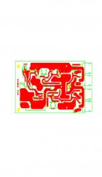
Here is thw new PCB layout incorporating variuos suggestions.
a: Provision for both high and low power version
b: Resistors in parallel with presets as suggested by Hugh.
c: Spade connectors for main connections
d: Pads at .2" for different type of connectors if required for input.
e: Vertical multiturn also supported as preset.
Your suggestions please.
Regards
Rahul
PS: Finally got around to making of JPEG. Thanks!
Attachments
The figures quoted by Christer are for fast fuses from Littlefuse. It seems like even a reputed firm like theirs can only give tolerances as wide as 50 ms to 2 s. Besides, using a fast fuse will lead to nuisance blowing. Which is why I'll get back on my soapbox and say again that the fuses aren't meant to protect from anything other than fire. If you want to save your drivers, it makes more sense to turn off the current quickly using a triac, SSR or something else. In any case, I guess this is not required on the amp board itself, it can be an outboard unit which turns off the supply current to the amps when anything goes wrong. Perhaps even a pair of MOSFETs will do, since they're not operating in the linear region, any old MOSFET pair (IRF640/9640 maybe) will work with minimum heating. Inserting a pair of small filter caps (perhaps 1000u or less) will help reduce the negative effects of the MOSFET on resistance.
Anyway, all this can be done outside the amp board, so probably this is not the best thread to be discussing this.
Anyway, all this can be done outside the amp board, so probably this is not the best thread to be discussing this.
Hi Rahul,
Your pcb is excellent; very neat, tidy, lots of thick tracks for heavy current, and even elegant. Like it a lot.
Question: where is the schematic, I'll just check off power dissipations to make sure nothing blows in hot Lucknow summers at full volume......
Roadkill, you make good points. However, I don't believe you are right with nuisance fuse blows. With 5A on my 55W AKSA I have never experienced a single nuisance blow. Economics enters all arguments here; the cost of crowbar protection for speakers is small, but in consumer electronics it is significant, and very few domestic high fi systems use it, preferring SOAR current limiting or relay series switching with DC detection, with all the attendant sonic penalty.
I might stand corrected if I use 3A, I'll check it out.
Cheers,
Hugh
Thanks Hugh,
I am greatful for your suggestions as well as appreciation that has boosted the spirit. I can now go ahead and ask my PCB wala to make a couple of them for test purpose.
The low power as well as high power version schematics had been posted earlier by Ashok have alook at the following pages:
http://www.diyaudio.com/forums/showthread.php?s=&threadid=30292&perpage=15&pagenumber=4
http://www.diyaudio.com/forums/showthread.php?s=&threadid=30292&perpage=15&pagenumber=6
I would now also start feeding the legends as well as begin working on PSU board.
Regards
Rahul
Wow! This thread gets more and more interesting. I am now tempted to join the gang in making a JLH.
I am just curious to know what heatsink rating would be needed for each channel.
Great layout Rahul.
Vivek
I am just curious to know what heatsink rating would be needed for each channel.
Great layout Rahul.
Vivek
Hugh, your amp never had nuisance fuse blows because the fuse was of a high enough rating. But at that rating, it will require more than 5A before the fuse blows fast enough to save the output drivers. By the time you drop the rating of the fuse low enough for them to react in time, fuse wire fatigue due to the constant thermal cycling which will occur during normal use will cause it to blow without any real fault. I believe Rod Elliot's site mentioned this somewhere, I'll go look for it now.
When this happens often enough, most folks will use a nail or a thick wire to bypass the fuse, and that's where the real danger begins.
Rahul, the PCB looks good to me. If you can, save the images in PNG or GIF format rather than JPEG, so they wont appear blurred.
When this happens often enough, most folks will use a nail or a thick wire to bypass the fuse, and that's where the real danger begins.
Rahul, the PCB looks good to me. If you can, save the images in PNG or GIF format rather than JPEG, so they wont appear blurred.
Dear Friends,
As I mentioned earlier call it a gift. I was sure from start we are into a good stuff. Thanks to all my friends for the support. I assure we alll would have something to be proud of at end.
Once again I say with the given specs seek something near abt in mkt you will be dissapointed. This is for now the ultimate that we can get.
I am once again greatful to Hugh not only for his appreciation but also his guidance in avoidance of any pitfalls.
Regards
Rahul
PS: Not to worry abt heatsink as I mentioned earlier we have a very good source, have a look at past posts. Your amp wont heat up my promise.
Dear Roadkill,
This for the first time I tried conversion direct from PDF . I will try all the other options. Still learning a lot in process.
Regards
Rahul
This for the first time I tried conversion direct from PDF . I will try all the other options. Still learning a lot in process.
Regards
Rahul
I agree with you on your entire analysis. Your posts make good reading. You should write a book called something like "Essays on audio design", where you can really do justice to your ability. 🙂 Honest; you explain very well.AKSA said:You are right; fuses do react rather too slowly, but let's look at the figures.
I have only one remaining question, but Roadkill has beaten me to it. Are fuse ratings accurate? I am not experienced enough to predict nuisance blows like Roadkill, but my question does sound similar to his.
But all said and done, if it came to building an amp, I'd probably go with the rail fuses as the best compromise of design effort, time, money and complexity. And if I suffered nuisance blowups, I'd probably shift to the next higher rating of fuses. This will be my approach for this JLH, as well as other modest-power Class B amps. The only place where I'll invest in good SSR-based switching will be if I have an array of amps to protect using just one switch (as in multi-amped speakers) or for expensive high-power amps. But then I guess high-power amps will usually be driving high-power speaker drivers (woofers, usually), which may not need very fast switching to protect them. So, I think I'm back to square one, sort of. Sigh.... 😕
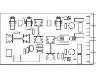
Boss, sorry to ask stupid questions, but where are the 5W power resistors? I can't see anything which looks like those large rectangular boxes which I expect you will have to use as emitter resistors for the paralleled-BJT OPS.Rahul said:............ here is the component layout.
My second point, which may be totally a matter of opinion, is about the (I presume) TO220 devices and their heatsinks. It may be possible that we may not all be able to get heatsinks of the design you've used. Some of us get rectangular finned heatsinks which look like black box-shaped things. To accommodate such flexibility, do you think it may be better to lay out the board such that these devices sit on the edges with their backs facing outwards, so that we get more flexibility to choose heatsinks of various kinds?
Hi!
Tarun:
First the pads have been spaced for TO247 the flatpack devices and not TO220. If we prefer to go in for TO-3 devices it would be simple matter to connect them to board thru short wire.
If we use a flat surface heatsink mounting becomes very simple. L bracket scheme can still be adopted . Keeping devices vertical I was not getting good clear space for wide track in major current conducting areas.
You will notice small rectangular boxes near transistors , pin configration is B- C-E. These rectangular spaces are for resistors 5W wirewound. These days they are available in flat package about 1" square and .15" thick, lead spacing is .35". You will find 5 of them 4 are used in high power version in Emitters of all 4 BJTs. the 5th is used in low power version at the collector of BJT connected to +ve rail. One can always vertically mount the regular axial type power resistors here.
Regards
Rahul
PS: BTW I will be reaching Mumbai on 11th at 11:35 by Sahara.
I've misled you totally. 🙂 What I was referring to was the three heatsinks on your PCB, not the OPS devices. I was not referring to the MJ15003/4. Now please re-read what I'd written, and see if I make sense? 🙂Rahul said:First the pads have been spaced for TO247 the flatpack devices and not TO220. If we prefer to go in for TO-3 devices it would be simple matter to connect them to board thru short wire.
Okay, if you're keeping space for 1" long resistors, that's fine. I wasn't sure of the scale of those rectangular boxes looking at the image. Thanks. 🙂You will notice small rectangular boxes near transistors , pin configration is B- C-E. These rectangular spaces are for resistors 5W wirewound. These days they are available in flat package about 1" square and .15" thick, lead spacing is .35".
Cool. I'll give you my phone number off-line. BTW, where will you be staying, what's your schedule like, etc?PS: BTW I will be reaching Mumbai on 11th at 11:35 by Sahara.
Tarun :
Now I get it. This again is not TO220 but the smaller package TO126 as we find for BD140, 2SC1162 etc. This variety of heatsink I feel is very common. You may have noticed them in Invertor boards. If any difficulty is encountered we can always put in the other parallel fin type.
Regards
Rahul
PS: Will send a mail later today.
Hi Roadkill,
Yes, you are right about the ratings; I suspect they are quite 'flexible' since we are dealing with a piece of metal which melts, not very accurate given the erratic currents through it, but yes, 5A has caused no nuisance blows.
In truth, as I believe I should have explained more clearly, the fuse was never intended to protect the output transistors. These devices are perverse creatures, manufactured after all in Japan, and as a rule they cheerfully lay down their lives to protect the fuses. In an imperfect, Bizarro world, this is probably to be expected.
Tarun,
Thank you for your gracious comments, Sire. Have a gander at my website, and you will see I have written quite a few papers on hifi design, some on very strange, ironic topics any Indian would be amused to read. (I'm conscious that Indians like irony, rather like the British. I'm happy to say Australians are in the same camp!)
Rahul,
Your design is excellent, though I confess I would prefer to see all components identified by number on the overlay. Is this possible? Any polarized components can be properly identified too; this saves mis-installation.
BTW, try this program, which is Freeware: http://www.irfanview.com
If you load in a jpg (and this program is designed for graphics display and manipulation) you can, with a simple keystroke, convert it to almost any other format, and even reduce size, colours, etc. I'd go for a gif; very economical. It's quick and efficient.......
Cheers,
Hugh
- Status
- Not open for further replies.
- Home
- Amplifiers
- Solid State
- [INDIA] Group Amp project