Ssr?
I was thinking of using a SSR in the path of the transformer primary, and putting the thermal switch in the path of the SSR's input circuit (i.e. the trigger circuit). For inrush current limiting and soft-start, I can put a second SSR to short the resistors. Only for the DC protection of the loudspeaker, I can retain the mechanical relay, for sonic reasons. I know the SSR will probably be more reliable than a mechanical relay. It will finally be a question of cost. For a 2A 250V SSR, I am quoted a price of Rs.200 or so on L.Road. I wonder what a 6A SSR will cost.
Any thoughts?
PS: And I didn't think your thoughts on protection circuits are off-topic; we were already debating the issue of protection circuits here...
How much should I expect to pay for such relays? And is the 30V the coil voltage or the max voltage across open contacts? Are there higher-current models too?roadkill said:There are PCB mounting hermetically sealed relays for telecom applications (rated to 10A at 30VDC) from (possibly Taiwanese companies) "Goodsky" and "Leone". I've used them for two of my amps for output thump protection. Work quite well...
I don't know whether your idea is related to what I've been thinking of, but I've always felt that a SSR (solid state relay) is better than a mechanical relay for switching the power supply for a power amp. Randy Slone's protection circuit, for instance, uses relays for soft-start (inrush current limiting) and in the loudspeaker output path for DC protection. He puts a thermal switch in the path of the loutspeaker output relay and removes the load from the power amp (makes it open circuit) if the heatsink temperature rises.One method I've always wanted to try is to use a controlled bridge (half or full), with SCRs. Then, by shutting off the gate drive, you can turn off the amp power in case there are problems such as overcurrent or heatsink overtemp.
I was thinking of using a SSR in the path of the transformer primary, and putting the thermal switch in the path of the SSR's input circuit (i.e. the trigger circuit). For inrush current limiting and soft-start, I can put a second SSR to short the resistors. Only for the DC protection of the loudspeaker, I can retain the mechanical relay, for sonic reasons. I know the SSR will probably be more reliable than a mechanical relay. It will finally be a question of cost. For a 2A 250V SSR, I am quoted a price of Rs.200 or so on L.Road. I wonder what a 6A SSR will cost.
Any thoughts?
PS: And I didn't think your thoughts on protection circuits are off-topic; we were already debating the issue of protection circuits here...
If I remember right, roughly Rs. 35. The spec mentioned is the maximum current rating of the contacts before arcing will destroy them. DC current creates a sustained arc, which is more damaging.How much should I expect to pay for such relays? And is the 30V the coil voltage or the max voltage across open contacts? Are there higher-current models too?
Suddenly, I'm beginning to wonder if this is exactly what you mean by hermetic sealing. There is no metal-to-metal welded bond, the relay's enclosed in plastic. The plastic enclosure however, cannot be removed, it's almost as if the bottom of the relay (where the pins are) is "potted" to the case. I've attached an image, the relay on the left is a DPDT with relatively tame ratings (1A, 30VDC), the one on the right is, well, you can read the ratings. Coil voltage is 12V, 5V is available but quite rare.
You can use a triac (eg: BT139) driven by an opto-triac (such as MOC3041) to control the AC to your transformer. This is much cheaper than using an SSR, but you must be very careful to not come in contact with the PCB or the triac (the TO-220 tab is live!) Same arrangement can be used on the secondary side also, since triacs have (compared to BJTs and MOSFETs), monstrous current ratings. The BT139 handles 10A! They also won't need much of a heatsink since the voltage drop will be small. If you're using a triac to short out the filter caps, use a series resistor (1 ohm or more), else your triac will be toast! Also, remember a triac will act as a non-latching switch only when AC is applied.
I know Randy's a personal god to many, but I find his scheme of thermal protection a bit strange. Heatsink temperature rise can't always be due to current flowing into the load. For instance, if the transistors have started to heat up due to the bias point changing (pot knob has moved, improperly designed thermal compensation, small heatsink or high ambient temp), then the amp quiescent current can cause the heatsink temp to get too high. It'll probably be better to shut off the amplifier's supply voltage.
The off-topic part was my rambling on about adjusting the supply voltage using a controlled bridge.
Hey, I found Elna capacitors on SP road. They are marked "ELNA for Audio". I have no idea if they are fake or not, I bought two, anyway (4700 uF, 100V), at Rs. 70 each. They have a black case, which is not what is pictured on Elna's website. Oh well, anyway I'm not much of a believer in "Capacitor Sound", especially when you're refering to the supply bypass caps.
Attachments
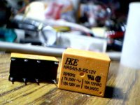
Thanks for the photo (ah, the joys of a digicam). That cleared up everything. I have almost exactly identical relays, bought for Rs.40 or so from Visha, light blue in colour, different brand. From the looks of them, I wouldn't use them in the speaker output path of anything bigger than a Gainclone... I am not sure they can handle higher currents reliably. But then again, maybe I'm being over-cautious... who among us pumps more than 2A into an 8Ohm speaker on a regular basis at home? That would be 32W! 😀roadkill said:If I remember right, roughly Rs. 35. The spec mentioned is the maximum current rating of the contacts before arcing will destroy them.
Your description exactly matches the relays I have. They are "epoxy potted" as they call them, I think. I also have some inexpensive toggle switches built this way. And yes, I'm sure this will make them hermetically sealed, maybe not for the switches but certainly for the relays.Suddenly, I'm beginning to wonder if this is exactly what you mean by hermetic sealing. There is no metal-to-metal welded bond, the relay's enclosed in plastic.
I have no clue about these things, but more experienced friends are uncomfortable using triacs on inductive loads (transformers?) because they say the damn triac never stops conducting with such loads, even when you switch off the gate. BTW, how much does a BT139 and that opto-triac cost?You can use a triac (eg: BT139) driven by an opto-triac (such as MOC3041) to control the AC to your transformer. This is much cheaper than using an SSR...
I'm quite a beginner in these matters, but is 10A a big rating? The MJ15003 seems rated for 25A continuous. Of course, the MJ15003 is more expensive than the SSR quote I got, let alone the BT139.... since triacs have (compared to BJTs and MOSFETs), monstrous current ratings. The BT139 handles 10A!...
As against making the load open-circuit? Yes, I agree too.. Somehow, cutting off the supply, specially on the primary side of the power transformer, seems to have a certain finality about it... You can be sure that no more power supply will reach anything, irrespective of where the problem is. 🙂... I find his scheme of thermal protection a bit strange. Heatsink temperature rise can't always be due to current flowing into the load. For instance, if the transistors have started to heat up due to the bias point changing, then the amp quiescent current can cause the heatsink temp to get too high. It'll probably be better to shut off the amplifier's supply voltage.
I'd asked him about this... I told him that instead of controlling the output relay, why doesn't he just pass the transformer primary through the thermal switch. He said that he considers it a serious bad-design issue to bring mains voltages anywhere near the electronics of the amp. Safety reasons. That's when I thought up the idea of using an "intermediary", the SSR, and controlling it through the thermal switch.
I've used similar relays (they were blue, too!) in both a gainclone and in the MOSFET amp I posted a link to some time back (measured 70W RMS into a resistor load of 6 ohms). So far, no problems. I switch the amp on and off roughly twice a day, it's been working fine for almost 3 months now.I have almost exactly identical relays, bought for Rs.40 or so from Visha, light blue in colour, different brand.
The BT139 is actually rated at a continuous RMS current of 16A (not 10A), hence peak current is 22.6A. All this in a TO-220 package... since they wont dissipate much heat if used correctly. The MOC3041 costs Rs. 10, the triac around 20 bucks (if I remember right). My experience with triacs is not very great, but I will try using them sometime in this application. BTW, the most important use for triacs is motor power control, which are highly inductive loads.I have no clue about these things, but more experienced friends are uncomfortable using triacs on inductive loads (transformers?) because they say the damn triac never stops conducting with such loads, even when you switch off the gate. BTW, how much does a BT139 and that opto-triac cost?
Randy's right about not bringing mains voltages near the output. You can take precautions such as heatshrink tubing over all mains wires, but just to keep Mr. Murphy happy, it'll be better to use an optically isolated control mechanism.
Tarun and friends ,
This really is Chinese stuff. As in case of most far east component I have taken a ball park figure of rating it at half its value. Now rated at 10Amp this is good for audio application but in most of the low cost UPS it fails miserably under supply fluctuautions. The cost here at Lucknow is Rs10/ for single contact and Rs25/ for double contact. another variant of 30Amp i think is also availabvle costing Rs60-65/.
Among better relays I have found OMRON Jap ones in almost all high end products a case similar to Alps pot.
Among Indian stuff OEN is good but unfortunately not many takers in audio line.
Regards
Rahul
Rahul, one of the relays I clicked a snap of is an Omron. I pulled it out of a junked modem... probably a good source for these? BTW, it had a 5V coil.
So far, I've not seen any hermetically sealed O/E/N relays, but I'll keep a lookout for them.
So far, I've not seen any hermetically sealed O/E/N relays, but I'll keep a lookout for them.
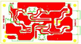
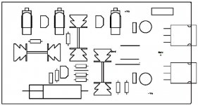
I looked at the layout, and had some questions:Rahul said:Thanks to Tarun and Ashok for their offer to help with the PCB layout. Ashok had it done as I had sent him the PDFs earlier.
- Are you sure we all want the low-powered version? I believe that if we design for the high-powered version, then those who want the low powered one can probably save on OPS devices by fitting just one pair, but the other way round won't be possible.
- I feel that if someone really wants to try using flat-pack OPS devices, they'll need the pads to be much closer to the edge than now. I think some changes can easily be made to bring the OPS devices closer to the edge.
- I remember reading somewhere on the 2003 JLH page that at least one of the CCS trimmers has to be a high-wattage version. Have you taken that into account? I seem to see three trimmers on the layout, and all are of the same size/shape. Just wondering...
- It would be nice to have legend printing on the draft layout images you post, so that we know what's what. Specially, I think it's necessary to ensure that the labels on the drafts match with the ones on the schematic (whichever schematic you're following), so that it becomes easier for us to review the layout intelligently.
In fact, right now, I can't even properly identify what some of the components are, because I can't recognize the shapes... they are not similar to shapes I'm used to seeing on other PCB packages. - Move the mounting holes to the "sides" instead of "lengthwise" as they are now. This will allow the OPS devices to move closer to the edge.
- Can you make provision to keep terminal blocks for all the leads? The idea of terminal blocks is "upward compatible" with people who don't want to use them, because such builders can always use the solder pads of the blocks and solder the wires directly to the board, without facing any problems.
- Since we'll have a PSU PCB, you can choose to keep the fuse on that PCB. Just in case.... it might help make this one's layout smaller or an easier job for you. In this amp's case it may not make much difference, but with normal Class-B amps with bridge+caps PSU, I prefer to keep the fuse on the PSU PCB so that multiple amps can be powered with one PSU with one pair of fuses.
- I'm guessing that the three vertical rectangles near the top edge are trimmers. If so, I'm glad you're choosing to use multi-turn trimmers. I prefer to use trimmers which have the adjust head pointing up, not sideways. They are easier to trim when the PCB is assembled, I feel. We get a certain type of trimmer here which has a vertical adjust screw and has three legs 0.1" apart. Rod Elliott too seems to use those trimmers for his P3A PCB. You can consider those. Of course, you'll have to check the high-wattage angle and decide something else for that one, if needed.
tcpip said:I looked at the layout, and had some questions:
- Are you sure we all want the low-powered version? I believe that if we design for the high-powered version, then those who want the low powered one can probably save on OPS devices by fitting just one pair, but the other way round won't be possible.
Very good idea. Going back to lower power is easy; 10W is not much, and will strain with a majority of conventional speakers.
[*]I feel that if someone really wants to try using flat-pack OPS devices, they'll need the pads to be much closer to the edge than now. I think some changes can easily be made to bring the OPS devices closer to the edge.[/B]
If the pad centres are 3mm from the edge of the heatsink, which aligns with the end of the flat pack semiconductor, you have ideal alignment.
[*]I remember reading somewhere on the 2003 JLH page that at least one of the CCS trimmers has to be a high-wattage version. Have you taken that into account? I seem to see three trimmers on the layout, and all are of the same size/shape. Just wondering...[/B]
By using a fixed, half watt resistor in parallel with a trimpot rated at say 100mW you can easily run acceptably low dissipation in the trimmer and achieve fine adjustment all at the same time. 1/Rt = 1/R1 + 1/R2; a 1K trimpot in parallel with a 100R resistor gives an adjustment range from close on 0R through to 91R. If the circuit is expected to optimize at around 83R, then the trimpot will be at half setting (500R), and it's dissipation will be very low.
[*]It would be nice to have legend printing on the draft layout images you post, so that we know what's what. Specially, I think it's necessary to ensure that the labels on the drafts match with the ones on the schematic (whichever schematic you're following), so that it becomes easier for us to review the layout intelligently.
In fact, right now, I can't even properly identify what some of the components are, because I can't recognize the shapes... they are not similar to shapes I'm used to seeing on other PCB packages.[/B]
These nice touches take many hours to get right, and represent a very high level of refinement which takes intensive labour and careful thought. You need a 'wish list', detailing precisely what's needed on the legend.
[*]Move the mounting holes to the "sides" instead of "lengthwise" as they are now. This will allow the OPS devices to move closer to the edge.[/B]
Try to keep the thermal centres of the OPS devices equally spaced along the heatsink.
[*]Can you make provision to keep terminal blocks for all the leads? The idea of terminal blocks is "upward compatible" with people who don't want to use them, because such builders can always use the solder pads of the blocks and solder the wires directly to the board, without facing any problems.[/B]
Try using pcb spade connectors, 6.3mm wide with two prongs which extend into the pcb. These are strong, and you can then use standard automotive push-on spade connectors which are very low resistance, highly reliable, and inexpensive.
[*]Since we'll have a PSU PCB, you can choose to keep the fuse on that PCB. Just in case.... it might help make this one's layout smaller or an easier job for you. In this amp's case it may not make much difference, but with normal Class-B amps with bridge+caps PSU, I prefer to keep the fuse on the PSU PCB so that multiple amps can be powered with one PSU with one pair of fuses.[/B]
Good idea. I put mine on the amp pcb, but Tarun's idea is better.
[*]I'm guessing that the three vertical rectangles near the top edge are trimmers. If so, I'm glad you're choosing to use multi-turn trimmers. I prefer to use trimmers which have the adjust head pointing up, not sideways. They are easier to trim when the PCB is assembled, I feel. We get a certain type of trimmer here which has a vertical adjust screw and has three legs 0.1" apart. Rod Elliott too seems to use those trimmers for his P3A PCB. You can consider those. Of course, you'll have to check the high-wattage angle and decide something else for that one, if needed.
Hope I'm making sense. 🙂 [/B]
The trimmers you refer to are the Bourns 3296W series, much copied around the world. I use nothing else, very good, very reliable, but beware cheap Chinese fakes, which are NOT reliable and cost almost the same........
Hope this is useful information. Great project Guys!!
Cheers,
Hugh
Wow, Hugh. Good to see you here. 🙂
Guys, if we get guidance from a guru like Hugh Dean, I think we have something to really preen about. 🙂
BTW, what devices do you feel we could use instead of the MJ15003/4, which may be better/safer (safer = higher current)?
Guys, if we get guidance from a guru like Hugh Dean, I think we have something to really preen about. 🙂
Yes, that's what I thought, but on first glance comparing the two topologies, I saw power resistors in the OPS of the higher-power one, but not on the lower-power one. I guess such differences will be minor and can easily be jumpered? This means that a common PCB should serve both types of requirements, I guess.AKSA said:Very good idea. Going back to lower power is easy; 10W is not much, and will strain with a majority of conventional speakers.
There's always a temptation to keep the pads further in, so that you can route thick traces to the collector and emitter pins from behind the device. I guess a compromise needs to be made here. The current distance is almost too much to allow direct soldering of the pins at all. But then, this entire point may be one of nit-picking, because it appears that all of us here have pretty much zeroed-in on the MJ15003/4 devices which are TO3 anyway.If the pad centres are 3mm from the edge of the heatsink, which aligns with the end of the flat pack semiconductor, you have ideal alignment.
BTW, what devices do you feel we could use instead of the MJ15003/4, which may be better/safer (safer = higher current)?
Bloody good idea. The only scary thought is what happens if the trimpot has to be set low.... it'll burn up, I guess. 🙁 But then again, maybe one can perform some trial runs with a trimpot, get the value that it needs to be set at, and then replace the trimpot with a half-watt or one-watt fixed resistor instead. With a Class A, very accurate control of bias current may not be needed, and this approach may reduce flexibility but increase reliability. What do you think?By using a fixed, half watt resistor in parallel with a trimpot rated at say 100mW you can easily run acceptably low dissipation in the trimmer and achieve fine adjustment all at the same time. 1/Rt = 1/R1 + 1/R2; a 1K trimpot in parallel with a 100R resistor gives an adjustment range from close on 0R through to 91R. If the circuit is expected to optimize at around 83R, then the trimpot will be at half setting (500R), and it's dissipation will be very low.
No, no, Hugh, I think we're talking about different things here. I merely wanted the component names (e.g. "C1", "R2", "VR1", etc) to be included in the PCB layout drafts which Rahul is posting onine. I use Eagle for PCB making, and the component names can be included at zero extra effort.These nice touches take many hours to get right, and represent a very high level of refinement which takes intensive labour and careful thought. You need a 'wish list', detailing precisely what's needed on the legend.
Just curious... why? Do hotspots develop in a heatsink which is supposedly a good heat conductor?Try to keep the thermal centres of the OPS devices equally spaced along the heatsink.
I have seen pics of a certain type of lugs, which are bolted on to the PCB (photo attached, three such lugs between the two big cans). Are these the type you are referring to?Try using pcb spade connectors, 6.3mm wide with two prongs which extend into the pcb. These are strong, and you can then use standard automotive push-on spade connectors which are very low resistance, highly reliable, and inexpensive.
Yes, that's the number on them. And I'm sure the ones I get here are not by Bourns, because they're far too inexpensive (about ten cents each, I think).The trimmers you refer to are the Bourns 3296W series...
Attachments
The JLH thread
Have you checked out this (huge) thread on the JLH amp? It's about two years long, and has 900+ posts. You may be able to get pointers to even PCB designs, and lots of caveats and mods from it. I feel any of us doing a PCB design of the JLH should at least go through this thread once. It'll be very painful re-inventing the wheel if we miss out some key point/recommendation.
There are many interesting things covered in this thread, including JLH derivatives made using MOSFETs. Who knows, this may let us even try the IRF250, and if that device works in this circuit, we may get a very inexpensive Class A option.
And even if we're not looking for groovy mods, I feel we will have to just "study the existing body of literature" on the subject, just to be sure we've covered our flanks.
Bourns 3296W is available in Bangalore, it's from a reliable source (called ,oddly enough, Cee Pee electronics) and costs a bit too (about Rs. 55, little over USD 1 each). They also have Bourns 3006P, which makes the amp a little difficult to adjust coz the screw is on the side.
The same shop, incidentally, has Bourn's "Helipot" series, wirewound 10 turn pots. Oh man, easily the best pots I've ever used. Just wish they had the same in single-turn...
Any ideas on where PCB mounted spade connector lugs are available? I'll try the local cable/wire shop where they have the spade connector part. Never seen the lugs, though.
And sorry if I'm getting in too late, but can someone post/email a link to the schematic for this amp (Linsley-Hood)?
Cool! I will now know where to look for them if I need them. 🙂roadkill said:Bourns 3296W is available in Bangalore, it's from a reliable source (called ,oddly enough, Cee Pee electronics) and costs a bit too (about Rs. 55, little over USD 1 each).
The last time I was in L.Road, I saw a whole bunch of them displayed in a shop window on the main road. Doesn't help you since you're in B'lore.Any ideas on where PCB mounted spade connector lugs are available? I'll try the local cable/wire shop where they have the spade connector part. Never seen the lugs, though.
Not a problem at all, but I don't need to post them ... they're already there in this thread. Just go back a few dozen posts and you'll see both the high-power version (post #89) and the lower-power one (post #47).And sorry if I'm getting in too late, but can someone post/email a link to the schematic for this amp (Linsley-Hood)?
Hi Tarun,
Thanks for your response; yes, you are right about the TO3 preference; actually superior for heat dissipation. Rather important in Lucknow!
I can't offhand think of a better device than the one chosen for the JLH (who died about two weeks ago, incidentally). They are very robust, and not too fast, and inexpensive, and widely used in pro-audio for precisely these reasons. Of the flat packs, I'd only use the MJL21193/94 series; they are very tough also, and not too fast, though a little faster. The JLH does not like overly fast outputs; it makes the amp unstable, so watch out!
We need to figure out power dissipations in the trimmer. I'll have a gander at the schematic.
I hope my picture comes though; this is the spade connector I was referring to. They are pressed into the pcb on two prongs, 1.3mm wide, and then soldered. They can be soldered to on the component side, OR used with conventional automotive female connectors. Very good value, inexpensive, and make for easy removal and maintenance, very important for DIY since all components on the board have a half life measured in months because the owner is always tweaking......
Cheers,
Hugh
Attachments
I now understand what I saw in this photo of the DACT linestage:Originally posted by AKSA
I hope my picture comes though; this is the spade connector I was referring to. They are pressed into the pcb on two prongs, 1.3mm wide, and then soldered....

See the signal connectors at the four corners (two for input, two for output). I don't know where to get them, and I don't know whether the shop-front I saw on L.Road here would include them in its list.
From your description it appears that these sit on two prongs like the fuse clips you've shown in your photo. I think they too have two parallel prongs which go into the PCB, right?
Tarun,
Right, they are secured in the pcb via 'legs', the same as the fuse holders. These pcb spades are made all over the world, including China. I wouldn't be at all surprised if there's a factory churning them out by the millions in India; I buy mine from China at about 5c US each, and that's not overly cheap.
However, they are zinc coated, highly conductive, and there is large contact area with an automotive female clip. As far as I can ascertain, they are not in any way audible, and they mean you can feed power and speaker connections with connectors, ready for easy removal.
Hope this helps; these spades are MUCH cheaper than the screw in types you displayed in an earlier post; they take up markedly less real estate and do the same job at lower cost. No brainer......
Cheers,
Hugh
Yes, I agree. Thanks to you, I've now understood what you mean. If I can standardise on these, I can probably eliminate Phoenix-type screw terminals from my future projects. What do you think about such terminals, BTW? Have your experiences been good?AKSA said:Hope this helps; these spades are MUCH cheaper than the screw in types you displayed in an earlier post; they take up markedly less real estate and do the same job at lower cost....
Dear Hugh,
Thank you Sir,
It is our pleasure and good fortune to have your feedback on this project.
To begin with this board is made using old EasyPC dos version. Each and every corner pad , track etc all has been painstakingly manually fed. No netlist here so no auto lengending. Despite all drawbacks it gives me the flexibility in placing pads and tracks as per my convenience. After careful study of schematics before the start of project much of it at back of my hands.
Sorry to know abt demise of JLH. I fondly remember him mention in an article series in E&WW ( Electronics and wireless world) about his FM tuner in his college days , a tube job and his own comments , his mother preferred the Ad of another commercial product. A true DIY spirit , something that will keep the fire burning within us for long. Perhaps this will be an Indian tribute to the hard work of JLH.
Friends glad to know that I had not commited any blunder in this first version.
As far connectors are concerened spade are the ones that I had in mind. Few Elektor design also use the same. Hugh here this pin type spade connectors are not available in mkt but originally I planned on another type with a screw in place of solder lug and spade at 45 Degrees, missing in layout is the screw hole. Square pads are there, while going thru layout also keep in mind that apart from track the PADS yellow in colour are also included in copper areas.
Preset: Thanks Hugh I find this padding of preset an excellent idea. I will put in addiitional resistors in parallel to the preset. The present pad combination caters to small and big horizontal preset also accomodating vertical ones as well as cermets for higher wattage and yes the multiturn.. Tarun I missed the multiturn variant suggested by you, I will incorporate the same in next layout ver.
On BJT distance layout I also feel this should be more nearer to corner for easy mounting , a 3mm distance makes it necessary to have the major tracks in front of BJTs , it is convenient if BJTs have resistors in base or emitters, but becomes difficult in other configration if we need to avoid jumpers. In next layout I will maximise ease of mounting and follow all these suggestions.
Thanks Hugh for your suggestion on output devices. We may source this in bulk so a good selection will benefit all DIYers.
BTW Hugh in summers it is indeed 48-50deg outside.
Roadkill thanks for your keen eyes in regard to this project. The schematics has been posted in one of early pages by Ashok , I suggest simply go thru them else there is a complete site dedicated to JLH by Geoff a google will get you there. Thanks again for the info on pots available at B'lore.
The new corrections should take one day but as you all know its the 31st of march, running, TAX man behind. 31st come and will have more free time.
Regards
Rahul
tcpip said:I looked at the layout, and had some questions:
- Are you sure we all want the low-powered version?....Hope I'm making sense. 🙂
i thought we were making a 28/56W version? am i on the same page? are we?
- Status
- Not open for further replies.
- Home
- Amplifiers
- Solid State
- [INDIA] Group Amp project