I would step back and ask why the amp is so sensitive to pcb layout. the problem might be somewhere else that made the amp this sensitive to small distributed parameters.
my experience is that a properly designed audio amp is quite robost (or it should be robost). I usually breadboard mine before actually building one on pcb and oscillation has been the least of my problems.
so I am a little bit at loss as to why this amp is so sensitive. I will look elsewhere for the problem.
I would endorse Graham's comments about proximity of output to input circuitry on a power amplifier. ANY amp will be compromised by bad layout practice, as only pFs of distributed capacitance around the input nodes will generate positive feedback. Even a large input cap will have sufficient surface area to pick up output radiation if the board is tight. Furthermore, lag comp should be minimized for best sonics, and with bad layout this too can send it over the edge through no fault of its own. And amps which have been aggressively manacled for maximum stability rarely sound good.
Cheers,
Hugh
Cheers,
Hugh
tlf9999 []
"
I would step back and ask why the amp is so sensitive to pcb layout. the problem might be somewhere else that made the amp this sensitive to small distributed parameters.
"
listen first of all the compensation of that amp is all over the place
thus all over the place is prone to oscillation, without compensation the amp turns into an oscillator...
"
I would step back and ask why the amp is so sensitive to pcb layout. the problem might be somewhere else that made the amp this sensitive to small distributed parameters.
"
listen first of all the compensation of that amp is all over the place
thus all over the place is prone to oscillation, without compensation the amp turns into an oscillator...
Thanks all for your insight and comments.
As Graham says it does appear that the amp is bursting into oscillation when increasing bias current. Perhaps, my PCB layout is not what it should have been for the GEM. However, most of my other PCBs are also "generally" designed along the same lines and I have had no problems.
I am not going to throw away this PCB. Perhaps, I will try to shield the input pair with a copper foil grounded. I suspect, the 10E resistor that separates quiet and noisy ground to be one cause of oscillation due to slight potential difference between the two ground points. Adding lower value capacitors to reduce inductance is also a must try.
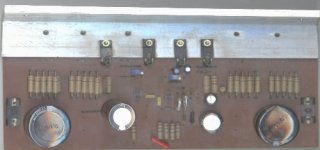
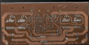
I am just attaching a scanned image of the PCB. The power transistors have been removed for checking. (Incidently I found only one 2SA1943 to be shorted and all other transistors are intact).
You can see on the track side that output is close to 1" away from the input components and the two are separated by what now is "quiet ground". Once I short the two ground points this will also be true ground.
I will post my findings after the next test run. Thanks.
As Graham says it does appear that the amp is bursting into oscillation when increasing bias current. Perhaps, my PCB layout is not what it should have been for the GEM. However, most of my other PCBs are also "generally" designed along the same lines and I have had no problems.
I am not going to throw away this PCB. Perhaps, I will try to shield the input pair with a copper foil grounded. I suspect, the 10E resistor that separates quiet and noisy ground to be one cause of oscillation due to slight potential difference between the two ground points. Adding lower value capacitors to reduce inductance is also a must try.
I am just attaching a scanned image of the PCB. The power transistors have been removed for checking. (Incidently I found only one 2SA1943 to be shorted and all other transistors are intact).
You can see on the track side that output is close to 1" away from the input components and the two are separated by what now is "quiet ground". Once I short the two ground points this will also be true ground.
I will post my findings after the next test run. Thanks.
Attachments
Hi Hugh,
Many thanks for your truths. Hope All's well with you.
______________________________________
Sadly there are those here who have made comment about things about which they have not first gained *direct* experience of;- ie. this amplifier.
I have deliberately chosen to keep the Gem signal path free of the 'compensation' arrangements that are so often necessary with other designs;- ie. 'compensating' capacitors or series resistor/device capacitance arrangements.
This amplifier is different, and thus it needs different construction arrangements too.
If the stated construction requirements are followed, it will run as intended - without oscillating - but this leaves no room for interpretation based upon experience with other designs.
I have just had further communication from Daniel Bosch. He also suffered oscillation, but now reports excellent drive into Apogees from 50V rails. He says it has been worth all the effort and will provide more feedback soon; I think triple AB outputs. He adds that he can't wait to have two monoblocks up and running.
He also concurs that my rules for construction *must* be followed, and suggests I re-emphasise them;-
1) input ground star earthing with short individual connections
2) power rail star connections directly from the 10mF - no shared supply feeds
3) a central output node star connection from output devices to nfb and output terminals
4) keep output star/wires away from input; input and speaker cables also.
______________________________________
Hi Samuel,
Making a single input ground should get rid of most of the oscillation risk, though I still feel that there is potential problem due to the small signal devices being surrounded by output stage voltage field.
This is where say 22pF of VAS C.dom compensation might be able to reduce gain at frequencies (rf) where just a few pF of stray coupling can induce positive feedback.
Still keeping my fingers crossed for you.
Cheers ......... Graham.
Graham Maynard said:Sadly there are those here who have made comment about things about which they have not first gained *direct* experience of;- ie. this amplifier.
Graham: have you only made comments on things about which you have first hand experience?
Graham Maynard said:I have deliberately chosen to keep the Gem signal path free of the 'compensation' arrangements that are so often necessary with other designs;- ie. 'compensating' capacitors or series resistor/device capacitance arrangements.
+
Graham Maynard said:This is where say 22pF of VAS C.dom compensation might be able to reduce gain at frequencies (rf) where just a few pF of stray coupling can induce positive feedback.
wouldn't ruin the basic design philosophy and the "appeal" of this amp? aka. keeping the signal path free of "compensation" arrangements that you have deliberately chosen for this amp.
I mean, this amp is supposed to sound excellent because of this "free compensation" which is why people build them. Woulding adding a "conventional" compensation scheme totally defeats the purpose of this amp? then why build it in the first place?
TLF,
You are a peculiar mixture of humble yet adversarial behaviour.
You condemn Graham because he has designed an amp which uses no compensation. Of course there is compensation!! It is instrinsic to the topology and dimensioning, and some lies within the Cob of the voltage amplifier as the depletion capacitance. That his particular layout requires no compensation is no guarantee that another's layout will be the same; Samuel has found that he needs perhaps a few pF to calm its savage breast.
Most VASs require at least 47pF of lag compensation. This design requires vanishingly small compensation. You would know this if you are as experienced as you appear. Going on about purist notions of 'defeating the purpose' and generally heaping derision on an extremely innovative and clever design merely shows you up as an ignorant street fighter.......
Please, give credit where it's due, read fully the very comprehensive thread, build the amp, tinker with it, and be bloody grateful this seminal design was made available gratis to combative dilettantes like you.
Cheers,
Hugh
AKSA said:You condemn Graham because he has designed an amp which uses no compensation.
I didn't condemn anyone for anything. I was just commenting on the seemingly ultra sensitivity of this amp to its pcb layout, which its constructors seem to report and which Graham seems to support.
AKSA said:Of course there is compensation!! It is instrinsic to the topology
In his own words, Graham disagreed with the above.
from Graham:
I have deliberately chosen to keep the Gem signal path free of the 'compensation' arrangements that are so often necessary with other designs;- ie. 'compensating' capacitors or series resistor/device capacitance arrangements.
do you think he wasn't telling the truth?
AKSA said:That his particular layout requires no compensation is no guarantee that another's layout will be the same; Samuel has found that he needs perhaps a few pF to calm its savage breast.
so maybe the correct statement is "this layout does not require compensation", not "this circuit / topology does not require compensation"?
did graham ever publish his pcb somewhere in this thread? I might have missed it.
It's rather obvious that Graham has designed an amplifier that pushes the performance limits at the expense of layout design and construction simplicity. Rather than be critical, we should be embracing the challenge of the implementation. This implementation will obviously require a little more than usual attention to RF principles.
FTR I had similar difficulty with a low Cob preamp design. I was able to lessen the problem by creating an RF ground plane and by inserting an F14 bead in the VAS emitter. However, the ultimate answer was to create a double sided board with RF shielding between stages (as well as input and output) In other words, if you consider the amplifier essentially a VHF amplifier and design / construct accordingly then parasitics from stray capacitance can be eliminated.
BTW, it can be of use to look at the frequency of the parasitic as well as the amplitude, and a CRO probe with resistor (or an RF probe) are valuable tools in determining the cause and hence a solution.
David Lewis said:It's rather obvious that Graham has designed an amplifier that pushes the performance limits at the expense of layout design and construction simplicity.
it sure sounds like that. If people knew this up front, it might have helped them design a more suitable PCB layout and minimized the problems they have encountered so far.
I think people need to be made aware of that up front, and it helps get more of the GEM amps built and working which I assume is what Graham wanted to do by publishing his amps.
if we didn't have this discussion, the same mistakes would have been repeated by more people who may end up in frustration and give up on this amp.
I wasn't been critical for the sake of being critical. I sensed that there is an issue (which you correctly identified ) but wasn't addressed and mentioned up until this point.
Graham has offered very detailed explanations and recommendations all along the way. He has answered every sincere question that has been posed. Relevant to the previous few posts he has published a proposed layout that addresses the stability issues, to wit:
http://www.diyaudio.com/forums/showthread.php?postid=702310#post702310
Constructive criticism, offered in the spirit of learning, is always welcome. Ill tempered comments, less so. Civility and respect is all that is asked.
Sheldon
http://www.diyaudio.com/forums/showthread.php?postid=702310#post702310
Constructive criticism, offered in the spirit of learning, is always welcome. Ill tempered comments, less so. Civility and respect is all that is asked.
Sheldon
A couple of simple questions (I think). With single output devices, the biasing is the same as indicated? Or would the bias for the AB pair be scaled? Other than output capacity, is there any reason to favor single or dual devices? My intended application would be 8 ohms, so I was thinking single. But could double up just to have flexibility.
Sheldon
Sheldon
I know this is a bit off topic, but I have been so impressed with what i have seen here that i feel i just have to ask it:-
Graham, have you done any design work with preamps? I am looking for a top quality design at the moment.
Or perhaps someone else has something thart has really knocked their socks off?
(Sorry for the departure off topic)
Regards,
William
Graham, have you done any design work with preamps? I am looking for a top quality design at the moment.
Or perhaps someone else has something thart has really knocked their socks off?
(Sorry for the departure off topic)
Regards,
William
tlf9999 said:it sure sounds like that. If people knew this up front, it might have helped them design a more suitable PCB layout and minimized the problems they have encountered so far..
Hi TLF,
I shelved my PCB early in the thread because Graham strongly recommended that his layout be followed because of compensation issues and possible oscillations.
DestroyerX's early implementation also required compensation caps and this was an issue with his layout.
In short, if we read through the thread, all the information is there.
Thinking again, building this amp would turn out to be a very valuable learning exercise because there are a few huddles to overcome.
Thanks Graham.
regards
Even wideband and RF amplifiers have compensation, whats
not known here is how much is needed
Graahm is great contributor to this forum, i hope my
comments havent discarage him from coming up
with the next version of gem it would be interesting
to see what comes next
cheers
not known here is how much is needed
Graahm is great contributor to this forum, i hope my
comments havent discarage him from coming up
with the next version of gem it would be interesting
to see what comes next
cheers
TLF,
Thank you for being circumspect and accepting criticism.
To all on this forum; Graham's design is a novel, low compensation amp. With scrupulous attention to detail, it's clearly possible to reduce formal, identifiable compensation to zero. However, there is still compensation in the circuit, otherwise it could not meet the Bode-Nyquist criteria for stability, viz less than unity gain at the upper pole. This is achieved by rolling off HF response in other, more subtle ways, and by choosing components, dimensioning and layout conducive to minimizing positive feedback. These are details you cannot see in the schematic, incidentally, and is what makes a good design truly great.......
If lesser layouts require compensation, it's likely to be very small, perhaps of the order of 10-30pF across the base/collector of the VAS. This is still markedly lower than 90% of amps out there in the market, and highly commendable.
Amp design comes up against this final frontier again and again. You need compensation to make it stable, but compensation impairs sonics. Any design which minimizes this compensation is likely to be tetchy with sub-optimized layouts; however, this is merely one way of viewing it. You could also say that Graham's amp achieves 100% stability with extremely low compensation; thus offering the prospect of scintillating sonic performance. As a general rule I've found that only current amplifiers do not require compensation - any amplifier with voltage gain needs it like a fish needs water. This is nonetheless a significant achievement, and Graham is guilty only of working at the bleeding edge of amp design without blowing his own trumpet. If there are those here who want a no-brainer DIY amp, this is probably not the one to choose.
William, I have a preamp design on my website which might fit your requirement, but it's not for free! There is even one in SA, in Port Elizabeth.
Cheers,
Hugh
Hi Graham and Carlos, thanks for the great amp. Here I have a few questions:
1. What is the minimum voltage rating for bootstrap capacitor (2200uF) assumming 42V rail?
2. Can I replace the lonely transistor (C3281) with non-complementary of the output transistors (A1358)?
3. Can I replace both transistors in the VAS section (C3421) with non-complementary of the driver transistor (A1358)?
4. What is the acceptable minimum value for feedback capacitor (4700uF)?
5. Can I just use VR of 2K (instead of the 1K) in the VAS section?
Thank you.
Hi All,
I used to communicate much via -diyAudio-
However, because of assumptions, attitude, non-constructive, erroneous, irrelevent, 'who supposedly said what' nit-picking, plus personally aimed non-technical argument (which the moderators still do nothing about), this has been the *only* thread I have followed for some months now. I no longer read the main index pages either, because I sure don't need the hassle that some members seem to delight in propagating almost every time I try to make useful contribution. I already have more than a full share of real-world problems to cope with at the moment, and thus tlf9999's Post#427 (which are like his personally named and unfounded hits on my contributions as in the JLH 10W class-A amplifier thread Post#1292) on this hitherto positive and good humoured thread, caused me to fully unsubscribe it.
My sole reason for remaining here has been to assist constructors with this circuit, and, because home based computers cannot mimic voltage field or circuit current induced oscillation, I remain interested to see what other versions might arise through hands-on development.
I have needed to advise Samuel that he might need a 'conventional' VAS base-collector compensation capacitor because he has constructed using a convenient layout, which leaves the input devices surrounded by a VAS/output stage voltage field.
The Gem can be made to work using conventional compensation, but, as *previously stated plus discussed and repeated* through this thread, it runs without need for additional components for signal/NFB path compensation. I eventually managed to draw out a suggested stripboard layout and posted it, whilst presently, we are of course still waiting for Barry to test his pcb.
Those who construct as stated, should be satisfied with the results.
Hi Hugh, David, PMA and Sheldon,
Your Posts give me hope.
In the past I have enclosed the entire small signal devices pcb of my JLH based amplifiers in an aluminium box.
Barry's pcb 'floods' the ground connection and thus double sided might not be necessary as long as the small signal transistors are mounted facing away from the power devices and output wiring.
Sheldon, I always assume that 8 ohm loudspeakers have dynamic current requirements far exceeding those of an 8 ohm resistor, thus I would not recommend a single pair of output devices at +/-36V unless high current H-pak types. A single pairing should work well at say +/-25V, though intuitively I would stick to 100mA/400mA bias. The class-AB crossover is class-A assisted, and the upper class-AB half is also upper class-A, so it is not as if a narrow optimum class-AB bias needs to be set up.
Hi Hihopes,
Pre-amps ? MM-disc yes, but a long time ago. General usage no.
CD/DAC outputs are good enough for direct driving these days, or of course an equaliser can be inserted to match personal choice/room/spkrs etc.
Cheers ......... Graham.
- Status
- Not open for further replies.
- Home
- Amplifiers
- Solid State
- Incredible quality amplifier by Graham, prepare your ears for it