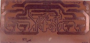
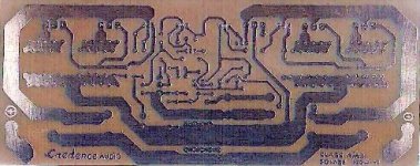
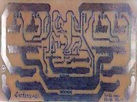
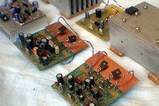
O.K. here is an attached scanned image of a hand made PCB for the GEM amplifier. Yes, the image quality is bad. In due course, I will post the picture of a fully assembled board.
All capacitors can be bypassed with film types of ample value (if needed). The input transistors and current source transistors are thermally coupled. Noisy and quiet grounds are separate. No wires to connect transistors that mount on heat sinks.
Though you cannot use the PCB as is, it should give a fair idea of how to make your own, even if you are using computer software.
Attachments
Design looks awesome! What about speakers?
Hey,
I have been into electronics for years, but I am new to audio design/build. I have searched through many amp designs and this one looks awesome. I would like to put a system together (I finally have some cash for one) and would like to build a couple of GEM monoblocks. What would you recommend speaker-wise (your personal opinion is welcome)? DIY or store bought are both ok, but DIY would be nicer. Thanks for any help.
Sean
PS Thank-you so much to Graham and Carlos and all you great guys for the GEM!
Hi All,
Good to see you keeping all of the communications in neat order Carlos !
We have another satisfied constructor - Daniel Bosch - though unfortunately he too suffered device failure whilst trying to set up the bias. I have thus produced the following write-up to go with the design for constructors to copy/paste and print off.
_______________________________________________________
This circuit developed out of my 30+ years of JLH class-A based
investigations.
The original 'simple' 1969 JLH class-A design provided excellent first cycle
accuracy through mid and high frequencies (dynamic clarity) because there
were no stabilisation components nor a series output choke, whilst the NFB
error correction was established via the input emitter (some describe this
as current feedback).
However it did generate rather a lot of heat, the damping was 'soft' at
lower frequencies and the positive slew was weaker in the presence of
loudspeaker system generated back-EMF at higher audio frequencies. I was
eventually able to improve upon the original JLH circuit by;-
1) adding a 'helper' class-AB output stage to substantially increase power
and efficiency, but leave sufficient class-A bias for real-time control
maintenance through phase shifted zero current class-AB crossovers;
2) adding a differential input stage for zero output voltage control, but
also fit a 10nF base-emitter capacitor for differential voltage operation at
audio frequencies, though with leading emitter routed feedback to maintain
circuit stability and NFB control above 20kHz;
3) adding a current mirror to obviate power-up thump, but also fit a 220nF
base-emitter capacitor to ensure stable 'source only' operation above audio
frequencies.
Thus, when compared to conventional circuits, one complete high frequency
phase change has been removed from the closed feedback loop in order to
minimise need for any additional stabilisation components that would
otherwise render the circuit inductive at audio frequencies. The original
JLH high frequency (current feedback) stability and simultaneously phase coherent
class-A control are retained.
This circuit was intended for 2SA1358+2SC5200 operation, yet it has been successfully constructed using other device types, including a single Sanken 2SA1216+2SC2922 pair in place of the paralleled ABs. (Try whatever is to hand, even very old types) Keep VAS, Zobel and
output related wires 5cm/2" away from input devices and wiring. Use a star
earth from the input location. Use star power distribution from each rail fused
10mF at the pcb. Use star output node connections. Parallel all large Cs
with smaller ones. Do not twist any extender e-b-c wires that might be used
out to heatsink mounted output stage devices. Mount VAS, drivers and the Vbe multiplier on the output heatsink for automatic temperature compensation.
Use multi-turn bias potentiometers. Adjust the class-AB pre-set to 50% but adjust the class-A pre-set to be a short circuit before the initial switch-on. I recommend 22 ohm per rail in place
of the fuses in case of error, and no output load for initial power-up testing. Check output zero is okay, but do not try to set up the bias currents. If all okay then insert fast 2A fuses and set up the quiescent bias currents, again without amplifier load. If all voltage checks okay after setting the bias, leave for an hour and recheck the bias currents - they are likely to have drifted upwards with temperature. Re-trim the bias currents then fit the final fast 6.3A fuses, and system test.
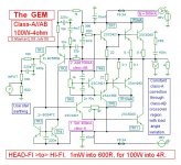
100W-4ohm (conservatively rated) is 50W-8ohm. For 70W/35W use 30V rails. For 50W/25W, 25V. For 100W-8ohm with higher voltage rails try a 47pF Miller
connected C.dom to the VAS, it should compensate for device/stability
changes with increased voltage, yet not adversely affect the class-A
operation in maintaining crossover continuity. Always bias from zero current
if you increase the rail voltage.
Insert a 0.22 ohm series output resistor to maintain stability when driving purely capacitive loads, and don't forget to bi- or tri-wire out to composite loudspeaker system sections and drivers in order to obviate single cable developed dynamic voltage drops with varying loudspeaker system generated back-EMFs, no matter how expensive your loudspeaker cable might be.
Graham Maynard.
Good to see you keeping all of the communications in neat order Carlos !
We have another satisfied constructor - Daniel Bosch - though unfortunately he too suffered device failure whilst trying to set up the bias. I have thus produced the following write-up to go with the design for constructors to copy/paste and print off.
_______________________________________________________
This circuit developed out of my 30+ years of JLH class-A based
investigations.
The original 'simple' 1969 JLH class-A design provided excellent first cycle
accuracy through mid and high frequencies (dynamic clarity) because there
were no stabilisation components nor a series output choke, whilst the NFB
error correction was established via the input emitter (some describe this
as current feedback).
However it did generate rather a lot of heat, the damping was 'soft' at
lower frequencies and the positive slew was weaker in the presence of
loudspeaker system generated back-EMF at higher audio frequencies. I was
eventually able to improve upon the original JLH circuit by;-
1) adding a 'helper' class-AB output stage to substantially increase power
and efficiency, but leave sufficient class-A bias for real-time control
maintenance through phase shifted zero current class-AB crossovers;
2) adding a differential input stage for zero output voltage control, but
also fit a 10nF base-emitter capacitor for differential voltage operation at
audio frequencies, though with leading emitter routed feedback to maintain
circuit stability and NFB control above 20kHz;
3) adding a current mirror to obviate power-up thump, but also fit a 220nF
base-emitter capacitor to ensure stable 'source only' operation above audio
frequencies.
Thus, when compared to conventional circuits, one complete high frequency
phase change has been removed from the closed feedback loop in order to
minimise need for any additional stabilisation components that would
otherwise render the circuit inductive at audio frequencies. The original
JLH high frequency (current feedback) stability and simultaneously phase coherent
class-A control are retained.
This circuit was intended for 2SA1358+2SC5200 operation, yet it has been successfully constructed using other device types, including a single Sanken 2SA1216+2SC2922 pair in place of the paralleled ABs. (Try whatever is to hand, even very old types) Keep VAS, Zobel and
output related wires 5cm/2" away from input devices and wiring. Use a star
earth from the input location. Use star power distribution from each rail fused
10mF at the pcb. Use star output node connections. Parallel all large Cs
with smaller ones. Do not twist any extender e-b-c wires that might be used
out to heatsink mounted output stage devices. Mount VAS, drivers and the Vbe multiplier on the output heatsink for automatic temperature compensation.
Use multi-turn bias potentiometers. Adjust the class-AB pre-set to 50% but adjust the class-A pre-set to be a short circuit before the initial switch-on. I recommend 22 ohm per rail in place
of the fuses in case of error, and no output load for initial power-up testing. Check output zero is okay, but do not try to set up the bias currents. If all okay then insert fast 2A fuses and set up the quiescent bias currents, again without amplifier load. If all voltage checks okay after setting the bias, leave for an hour and recheck the bias currents - they are likely to have drifted upwards with temperature. Re-trim the bias currents then fit the final fast 6.3A fuses, and system test.
100W-4ohm (conservatively rated) is 50W-8ohm. For 70W/35W use 30V rails. For 50W/25W, 25V. For 100W-8ohm with higher voltage rails try a 47pF Miller
connected C.dom to the VAS, it should compensate for device/stability
changes with increased voltage, yet not adversely affect the class-A
operation in maintaining crossover continuity. Always bias from zero current
if you increase the rail voltage.
Insert a 0.22 ohm series output resistor to maintain stability when driving purely capacitive loads, and don't forget to bi- or tri-wire out to composite loudspeaker system sections and drivers in order to obviate single cable developed dynamic voltage drops with varying loudspeaker system generated back-EMFs, no matter how expensive your loudspeaker cable might be.
Graham Maynard.
Attachments
Lets hope this will appear better 🙂
*****************************
This circuit developed out of my 30+ years of JLH class-A based investigations.
The original 'simple' 1969 JLH class-A design provided excellent first cycle accuracy through mid and high frequencies (dynamic clarity) because there were no stabilisation components nor a series output choke, whilst the NFB error correction was established via the input emitter (some describe this as current feedback). However it did generate rather a lot of heat, the damping was 'soft' at lower frequencies and the positive slew was weaker in the presence of loudspeaker system generated back-EMF at higher audio frequencies. I was eventually able to improve upon the original JLH circuit by;-
1) adding a 'helper' class-AB output stage to substantially increase power and efficiency, but leave sufficient class-A bias for real-time control maintenance through phase shifted zero current class-AB crossovers;
2) adding a differential input stage for zero output voltage control, but also fit a 10nF base-emitter capacitor for differential voltage operation at audio frequencies, though with leading emitter routed feedback to maintain circuit stability and NFB control above 20kHz;
3) adding a current mirror to obviate power-up thump, but also fit a 220nF base-emitter capacitor to ensure stable 'source only' operation above audio frequencies. Thus, when compared to conventional circuits, one complete high frequency phase change has been removed from the closed feedback loop in order to minimise need for any additional stabilisation components that would otherwise render the circuit inductive at audio frequencies. The original JLH high frequency (current feedback) stability and simultaneously phase coherent class-A control are retained. This circuit was intended for 2SA1358+2SC5200 operation, yet it has been successfully constructed using other device types, including a single Sanken 2SA1216+2SC2922 pair in place of the paralleled ABs. (Try whatever is to hand, even very old types) Keep VAS, Zobel and output related wires 5cm/2" away from input devices and wiring. Use a star earth from the input location. Use star power distribution from each rail fused 10mF at the pcb. Use star output node connections. Parallel all large Cs with smaller ones. Do not twist any extender e-b-c wires that might be used out to heatsink mounted output stage devices. Mount VAS, drivers and the Vbe multiplier on the output heatsink for automatic temperature compensation. Use multi-turn bias potentiometers. Adjust the class-AB pre-set to 50% but adjust the class-A pre-set to be a short circuit before the initial switch-on. I recommend 22 ohm per rail in placeof the fuses in case of error, and no output load for initial power-up testing. Check output zero is okay, but do not try to set up the bias currents. If all okay then insert fast 2A fuses and set up the quiescent bias currents, again without amplifier load. If all voltage checks okay after setting the bias, leave for an hour and recheck the bias currents - they are likely to have drifted upwards with temperature. Re-trim the bias currents then fit the final fast 6.3A fuses, and system test. 100W-4ohm (conservatively rated) is 50W-8ohm. For 70W/35W use 30V rails. For 50W/25W, 25V. For 100W-8ohm with higher voltage rails try a 47pF Miller connected C.dom to the VAS, it should compensate for device/stability changes with increased voltage, yet not adversely affect the class-A operation in maintaining crossover continuity. Always bias from zero current if you increase the rail voltage. Insert a 0.22 ohm series output resistor to maintain stability when driving purely capacitive loads, and don't forget to bi- or tri-wire out to composite loudspeaker system sections and drivers in order to obviate single cable developed dynamic voltage drops with varying loudspeaker system generated back-EMFs, no matter how expensive your loudspeaker cable might be.
Graham Maynard.
*************************
Happy to see you discovered the simple way Graham...i also use Word pad
To produce some "commented images"...to insert arrows, to produce simple sketches, to copy and paste images from the screen, using Caps lock and Print screen buttons.
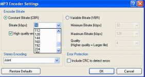
Other simple and wonderfull product, freeware, to all of us.... is the Wave pad.... this small program is capable to make audio recordings, the length you want, recordings made in wave format, you can adjust if stereo of mono, also you can adjust if you want small sample or the 96000 maximum sample.
After that you can save as MP3 and other formats, again you can choice if you want 8K to 512K sample to MP3..... normally i use 16K for voice and 256k for music.
This program is helping me to communicate with a lot of friends using audio....as i can make 30 minutes of good audio, only voice and monaural, and the size will be around 2.5 Megabytes....this way, audio mails are beeing done, when voice is better than only typing...voice is more personal, more intimate and give us more informations about the other side feelings.
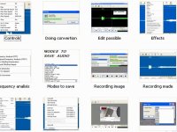
All resouces related edition, equalization is perfect, as you can cut from 8000 to 8200 without disturb other frequencies, for instance...you can insert echo or reverberation, change speed, reduce or increase speed, you can cut, edit, mix and all needed tools you can have for audio.... spectrum analiser and perfect waveform is shown....highly recomended...small, 400K program and it may be limited somewhere, but really, this limitation never disturb me, as i do not use that capacity, i also do not know where is the program limitation....i am using for 2 years, and the program not disturbing me asking me to buy, to update, upgrade, to go to their site to see new programs...nothing!.... perfect!
Thank you the expanded informations Graham...in my feelings, because my respect on you, also my respect to Hugh Dean...when you start to write, both of you, everything turns silence, and only your typped words enter my brain.... authority of the ones that really know what are doing.
regards,
Carlos
To produce some "commented images"...to insert arrows, to produce simple sketches, to copy and paste images from the screen, using Caps lock and Print screen buttons.
Other simple and wonderfull product, freeware, to all of us.... is the Wave pad.... this small program is capable to make audio recordings, the length you want, recordings made in wave format, you can adjust if stereo of mono, also you can adjust if you want small sample or the 96000 maximum sample.
After that you can save as MP3 and other formats, again you can choice if you want 8K to 512K sample to MP3..... normally i use 16K for voice and 256k for music.
This program is helping me to communicate with a lot of friends using audio....as i can make 30 minutes of good audio, only voice and monaural, and the size will be around 2.5 Megabytes....this way, audio mails are beeing done, when voice is better than only typing...voice is more personal, more intimate and give us more informations about the other side feelings.
All resouces related edition, equalization is perfect, as you can cut from 8000 to 8200 without disturb other frequencies, for instance...you can insert echo or reverberation, change speed, reduce or increase speed, you can cut, edit, mix and all needed tools you can have for audio.... spectrum analiser and perfect waveform is shown....highly recomended...small, 400K program and it may be limited somewhere, but really, this limitation never disturb me, as i do not use that capacity, i also do not know where is the program limitation....i am using for 2 years, and the program not disturbing me asking me to buy, to update, upgrade, to go to their site to see new programs...nothing!.... perfect!
Thank you the expanded informations Graham...in my feelings, because my respect on you, also my respect to Hugh Dean...when you start to write, both of you, everything turns silence, and only your typped words enter my brain.... authority of the ones that really know what are doing.
regards,
Carlos
Attachments
Wave pad can be found here, really freeware
A very good small program..... works very well.
http://www.nch.com.au/wavepad/
regards,
Carlos
A very good small program..... works very well.
http://www.nch.com.au/wavepad/
regards,
Carlos
Attachments

Mr. Graham,
This is very nice of You and most useful for us, however You write it... thank You
regards
sunny
This is very nice of You and most useful for us, however You write it... thank You
regards
sunny
Everybody loves Sunrise... Sun is life!...well, Graham is having problems, so
He is not tracking the thread those last two days.
His Mother in Hospital..... and this is terrible, mine already gone...and i do not envy no one that have alive mother, because hurts too much when those lovely womans go away from us.
But Barry Husbands are working hard with boards, and sending to Graham to evaluation, i am receiving copies too.... Graham goes suggesting some small modifications and Barry is beeing kind to make the way Graham wants...very kind from you Barry, very cooperative, you are a great guy!
When he return from this terrible hush he is living those days, i am sure Graham will return to track his thread, and Barry's last board version will be published.
Everyone that wanted some help, related construction or some details, even adjustments, can write me, i will try to help or will ask Graham to help you. Keep clear to you guys, that you do not need to understand deeply electronics to construct, we are here to help you, and you can answer the same thing once, twice, three times or even more times..... till you understand the adjustment method or something confused related the amplifier operation.
I want to tell you to feel yourself confortable to ask everything you need, and do not be ashamed, as i do not know a lot of things too... and i have asked three, four times or more, related many things till understand a little.
Having informs that a single person is constructing GEM, we will be following the thread and keeping it alive, it will be very near the main daily page.
nanabrother@yahoo.com
regards,
Carlos
Attachments

My amplifiers production is running, all those are researches, old circuits modified.
Barry is near the board research, Graham is feeling better and i am waiting someone that already constructed to hear if they like it or not.
My God!.... if not satisfied i will be called "Charlotte"...well...no one is so bad related hearing to not apreciate this one.
regards,
Carlos
Barry is near the board research, Graham is feeling better and i am waiting someone that already constructed to hear if they like it or not.
My God!.... if not satisfied i will be called "Charlotte"...well...no one is so bad related hearing to not apreciate this one.
regards,
Carlos
Attachments
Oh I wish that I could do like You ..... I am moving to another appartment and that 😡 preamplifier I am working on is still on the run (trying to catch 'im finally to work like it should)..... but don't worry I constantly keep my eye on this one for news and everything so - this is my next project (but I think in winter (europe) it will come =) since I have much to do in new appartemnt 🙁
p.s. like the picture and would like to see more 🙂
nice avatar
p.s. like the picture and would like to see more 🙂
nice avatar
GEM Compact PCB
Hi Everyone,
Sorry for the time taken to get as far as this PCB.
First my total thanks to Graham for his technical guidance and Carlos for his relentless encouragement. Without either I would never have got this far.
In the following postings I hope to publish the latest layouts for Graham's GEM amplifier.
With each posting I will add brief notes to help identify any key area of interest or concern.
As always feel free to comment. I am not very good at taking critism but I am learning to take it as well as drive this CAD package.
My next step is to build the PCB over the next few days and then update the PCB with my findings. Of course I will publish them on the forum here. So if you want to reduce your risks wait a while before etching your FR4.🙂
GEM Compact Amplifier PCB
What follows is the layout of the components that are not located on the heatsink as per Grahams previous notes. This enables this PCB to be compact and hopefully sound good. Where connections are made between the PCB and the components on the heatsink I have used KX# points. You can choose whether you wish to use multiple connections from the PCB or just a single wire.
The layout shown is as if you are looking through the top of the PCB down to the bottom. I will show a mirrored version next for those that need this instead for their etching.......
As you can see the ground plane is maximised so when the PCB has etched please make sure that there are no unwanted slivers of copper remaining. I know it is very difficult to resist the urge to apply power as quickly as possible but patience usually pays off more often than speed.
Attachments

GEM Compact Amplifier PCB
Next the identification for the PCB.
Watch R17 it is a little long.....🙂
Whilst it's not a special resisitor in terms of value it was needed to be about 55mm in length to maintain the integrity of the layout.
Any bright ideas welcome!
Many of you will have the same preference as Graham ans want to wire coax to the phono (RCA) socket pads on the PCB. That's fine.
Attachments
- Status
- Not open for further replies.
- Home
- Amplifiers
- Solid State
- Incredible quality amplifier by Graham, prepare your ears for it