Hi,
Knock test is not very relevant as it doesn't represent what happen within the wall ( distribution of 'modes' through the panel).
What you describe ( with lead sheets) is a 'crude' CLD or a brute force approach to damping.
I won't say it won't work as i've applied this to architectural decoupling and is effective in this case, however not sure that another more subtle approach isn't more effective in case of cabinet.
And about damping of the enclosure itself. I wan't to dampen the walls of the midrange chamber. I used butyl matts on my current pair. And this might not be a very scientific way to test but when I gave the panels a simple knock I couldn't hear a difference between with and without the butyl. So I really doubt if it's any effective.
What I was thinking about doing is having a heavy mass stuck to the walls with a soft rubbery material inbetween. I was thinking about 3 mm plates of lead with a rubbery foam adhesive, I'd still have to find what exactly. I think this would be a far more effective way. Appart from it's heavy mass the lead itself is very well damped as well. PMC does the same thing on their Fenestria speaker with the side walls.
An alternative to lead might be to use mass loaded vinyl if you want to add weight while not taking up a lot of space/volume.
Isomat TS | Isolatieplaat
Often used as a sound blocker with a layer of neoprene between it and the surface it's used upon.
See: How Is Mass Loaded Vinyl Used in Soundproofing? | Acoustical Solutions
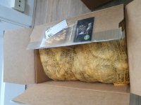
Attachments
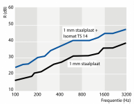
This graph is not representative for damping of a midrange enclosure. A rising damping with increasing frequency means that the sound transmission mechanism is in the mass controlled frequency range. Then only mass counts. So this graph tells us that Isomat TS 14 has a mass.
Midrange enclosures do not fully operate in this frequency range, they also operate at and below frequencies at which panel resonances occur. Then stiffness and damping also count.
Midrange enclosures do not fully operate in this frequency range, they also operate at and below frequencies at which panel resonances occur. Then stiffness and damping also count.
Last edited:
One can simply use it as added mass, or you can decouple it from the wall you want to treat and have it work more effectively as a sound blocker.
I just discovered there is a cork material that also has bits of rubber mixed in. It might be a good material as a middle layer of a sandwich damping system?
"Sorbothane" (a type of poly' rubber) is very good for absorbing vibrations. I think it needs to be under some compression to work best.
McMaster-Carr
McMaster-Carr
"Sorbothane" (a type of poly' rubber) is very good for absorbing vibrations. I think it needs to be under some compression to work best.
McMaster-Carr
McMaster-Carr
For bitumen sheets added to box walls they need to be as thick or thicker then the box wall to be effective, so bbc style thin walls is needed to be practice
Last edited:
Yes, the 34mm dome would have some things going for it over 25mm.
Funny how we see things differently, I do think the 25mm be-tweeter looks superior over the 34mm, at least on paper. I have not heard any of them though
Better is not a technical description, but the 34 is probably better in the low-end and the 25 is better in the top-end of it's response, if we compare these two. In other words, the 34 goes lower and the 25 goes higher in the spectrum. The 34 probably can play louder without strain, if that's matters.
Last edited:
Well surprisingly enough the 34 mm BliesMa is just as good at high frequencies as the 25 mm Scan-Speak. If you look at FR and disperion measurments it performs just as good.
I figered out how I'm going to do the damping I'm gonna keep it simple and damp the panels by using a dampening adhesive between the panels and bracing. Very simple yet probably one of the most effective ways to dampen these stiff walls. Like KEF does.
Ok, I'll lay it out on the table. Not that I've used this tweeter, but there are three things.Funny how we see things differently, I do think the 25mm be-tweeter looks superior over the 34mm, at least on paper. I have not heard any of them though
One is the directivity, a little narrowing at the top can be a nice thing.
Another is the potentially lower crossover. Not that a crossover done well should be a problem, but pushing it closer to 1k is not a bad thing.
And thirdly, I like the thought of a larger voice coil, similar to compression drivers.
Of course there is also the potential for dome breakup.
Funny how we see things differently, I do think the 25mm be-tweeter looks superior over the 34mm, at least on paper. I have not heard any of them though
In what aspect do you think the SS exceeds the BliesMa?
Of course there is also the potential for dome breakup.
Lukily that problem is being dealt with by the use of beryllium.
The aluminium 34mm Bliesma has exceptionally good dispersion at (very) high frequency. The beryllium - not so much.
The 25mm Bliemas have a face plate of about 70mm; the 34mm has 104mm. The smaller face plate is a serious plus in my eyes: Smaller c2c, easier to put on a baffle without much diffraction (as long as no waveguide is used).
So I would conclude that at around 2000 Hz crossover the 25mm will be probably "better" in practice (also depending on SPL requirements, obviously), especially with regard to potential diffraction problems. Of course, the 34mm can go lower - but as I said, with those it remains a serious challenge to minimize diffraction (on baffle widths in the range between ~200mm to ~~300mm at least) ...
Don't think the 34 mm beryllium has that big of a disadvantage to the 25 mm in despersion. It's actually quite on par with both the 25 mm SS. The 34 mm aluminium and 25 mm berylliuim BliesMa does actually have an advantage. But I honestly think the 34 mm beryllium when listening will be preferable with it's extremely low distortion and extreme speed, together with it's still very good dispersion.
left to right: 34 mm BliesMa, 25 mm BliesMa, 25 mm SS
left to right: 34 mm BliesMa, 25 mm BliesMa, 25 mm SS
Attachments


Last edited:
I figered out how I'm going to do the damping I'm gonna keep it simple and damp the panels by using a dampening adhesive between the panels and bracing. Very simple yet probably one of the most effective ways to dampen these stiff walls. Like KEF does.
Dr E Geddes would i'm sure agree.
Wise choice imho.
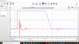
Today is measuring day! I managed to move my speakers down two stairs to the living room were I have a lot more space. And now I'm finally getting impuls graphs as I would expect them and the resulting frequency response after gating makes sence.
Time to get them rockin'.
Time to get them rockin'.
Attachments
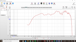
Yes, that does now make sense ! That 4 to 6kHz hump definitley needs to be tamed. Maybe the one higher up as well - this is a matter of taste. And as a general tendency your response is rising with frequency. Most people favour a response that is slightly dropping with rising frequiency.
Regards
Charles
Regards
Charles
- Home
- Loudspeakers
- Multi-Way
- In need of warmth