^^^^^^^^ that.
As of:
As of:
resonate
rĕz′ə-nāt″
intransitive verb
- To exhibit or produce resonance or resonant effects.
You are failing the very first definition 😱
The other two are more in the emotional realm, not applicable here.
^^^^^^^^ that.
As of:
You are failing the very first definition 😱
The other two are more in the emotional realm, not applicable here.
No, the other two are the important ones... you are mising the
^^^^^^^^ that.
As of:
You are failing the very first definition 😱
The other two are more in the emotional realm, not applicable here.
- To evoke a feeling of shared emotion or belief.
- To correspond closely or harmoniously.
Nope.. you are missing the point.... the third one is the important one...
Besides, you have NO sense of humor whatsoever.
If you are trying to convince us that "harmoniously"
https://dictionary.cambridge.org/dictionary/english/harmoniously
"harmoniously
adverb
uk /hɑːˈməʊ.ni.əs.li/
us /hɑːrˈmoʊ.ni.əs.li/
harmoniously adverb (pleasantly)
in a friendly and peaceful way:
We worked together very harmoniously.
In Ethiopia, Muslims and Christians live harmoniously together."
means the same or is in any way related to "harmonics" or even worse, to "harmonic distortion"
you are set for a rude awakening.
As of "humour" ..... tell a joke and we´ll laugh 😉
Random babblings? .... not that much.
Your self image perception must be very low, desperately trying to get attention, ........ even negative attention.
If you are trying to convince us that "harmoniously"
https://dictionary.cambridge.org/dictionary/english/harmoniously
"harmoniously
adverb
uk /hɑːˈməʊ.ni.əs.li/
us /hɑːrˈmoʊ.ni.əs.li/
harmoniously adverb (pleasantly)
in a friendly and peaceful way:
We worked together very harmoniously.
In Ethiopia, Muslims and Christians live harmoniously together."
means the same or is in any way related to "harmonics" or even worse, to "harmonic distortion"
you are set for a rude awakening.
As of "humour" ..... tell a joke and we´ll laugh 😉
Random babblings? .... not that much.
Your self image perception must be very low, desperately trying to get attention, ........ even negative attention.
Enough.... you're stuck in your ways.... I can accept that, but you are getting borderline insulting here. Stop....
 We can move forward now or we can take this further. Which is it to be?
^^^^^^ That.
Me?
Together with others already answered the OP question to the best of my knowledge, hope having helped him, that´s what matters.
Anything else, not worth pursuing, specially given the meager results.
Tons interesting threads around worth reading and , if possible, contributing something.
Me?
Together with others already answered the OP question to the best of my knowledge, hope having helped him, that´s what matters.
Anything else, not worth pursuing, specially given the meager results.
Tons interesting threads around worth reading and , if possible, contributing something.
Let me have a go at this.
A simple measure of distortion is THD+N meaning total harmonic distortion plus noise.
We take and amplifier and apply a 1Khz tone at a given power level. 1% power and rated power are useful levels. Other test frequencies can be useful in some cases.
We subtract the 1khz tone from the output and we are left with things we do not want. We may express the leftover stuff as a percentage of the total.
Noise will usually be evenly distributed across the frequency range.
The other distortion products are usually called harmonic products. They usually exist at multiples of the original frequency for example 2K(octave), 3K(third), 4K and so on for a 1K test tone.
Post #6 with the graph tries to say what kind of distortion products exist and not just give a percentage. The line at 1K shows the test signal. The top of the line is the actual level. We ask how much lower is the second compared to the fundamental and so on. We found that some amplifiers with about the same distortion numbers can sound different. Amplifiers with a little bit of second or third harmonic distortion just sound like a note one octave or third was added and it is not so bad. Some amplifiers can add maybe 7th and 9th harmonic tones and a little of that can sound more like chalk board scratchings.
Let me have a go at this.
A simple measure of distortion is THD+N meaning total harmonic distortion plus noise.
We take and amplifier and apply a 1Khz tone at a given power level. 1% power and rated power are useful levels. Other test frequencies can be useful in some cases.
We subtract the 1khz tone from the output and we are left with things we do not want. We may express the leftover stuff as a percentage of the total.
Noise will usually be evenly distributed across the frequency range.
The other distortion products are usually called harmonic products. They usually exist at multiples of the original frequency for example 2K(octave), 3K(third), 4K and so on for a 1K test tone.
Post #6 with the graph tries to say what kind of distortion products exist and not just give a percentage. The line at 1K shows the test signal. The top of the line is the actual level. We ask how much lower is the second compared to the fundamental and so on. We found that some amplifiers with about the same distortion numbers can sound different. Amplifiers with a little bit of second or third harmonic distortion just sound like a note one octave or third was added and it is not so bad. Some amplifiers can add maybe 7th and 9th harmonic tones and a little of that can sound more like chalk board scratchings.
You know, I wonder how proper is that THD measurement based solely on the 1Khz input signal.
If the harmonic distortion is a function of fundamental frequency, that is, different levels and envelopes for different frequencies for the fundamental input signal, then how can we fully measure THD?
Example, take a device that has high THD in the bass but a clean treble, or viceversa... Surely those devices must sound quite different! How can we measure that? A waterfall? I have NEVER seen such a measurement published.
THD vs frequency graph is published almost all the time. Yet you have never seen it?
Hmm.. the THD that I see is based on a frequency spectrum based on a 1Khz input signal.
Do they do this for a swept fundamental input signal.... do they sweep the fundamental input signal from 20Hz to 20Khz and then look at the harmonic spectrum of the distortion, and measure how it changes with the frequency of the input signal?
That will be a WATERFALL graph. The 'z' coordinate would be the frequency of the input signal for the harmonic distortion plot.
THD vs frequency graph is published almost all the time. Yet you have never seen it?
That graph is not what I'm referring to, I've seen it, naturally. But that graph just shows the scalar THD number - a calculated dimensionless number (a ratio).
Not the actual spectral decomposition which would be a vector space in the frequency domain.
What I would like to know is the frequency spectrum of the distortion. There could easily be filters that affect the harmonic decomposition so the distortion very differently across the frequency spectrum. A high pass filter, for example, would lower the distortion harmonics in the lower frequencies... so the measured harmonic distortion spectrum for a low frequency fundamental might be low in 2nd and 3rd but high in the 5th and 6th... and so on...
It might not be important, but I would still like to see it. It might explain why amplifiers that "measure" the same, still sound different.
Last edited:
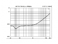
I do a sine sweep whenever I take measurements.
Here is an example:

You specify the parameters (how many steps for example) and the software will run each frequency and measure the distortion products.
This one was taken during prototyping, so is incomplete but should give you an idea.
Here is an example:
You specify the parameters (how many steps for example) and the software will run each frequency and measure the distortion products.
This one was taken during prototyping, so is incomplete but should give you an idea.
I think its quite important to think distortion and how filters affect, but not sure if it matters what the graphs show as long as they can be evaluated for the purposes of reducing non-linear distortion? What extra information would be provided with such graph for practical application?That graph is not what I'm referring to, I've seen it, naturally. But that graph just shows the scalar THD number - a calculated dimensionless number (a ratio).
Not the actual spectral decomposition which would be a vector space in the frequency domain.
What I would like to know is the frequency spectrum of the distortion. There could easily be filters that affect the harmonic decomposition so the distortion very differently across the frequency spectrum. A high pass filter, for example, would lower the distortion harmonics in the lower frequencies... so the measured harmonic distortion spectrum for a low frequency fundamental might be low in 2nd and 3rd but high in the 5th and 6th... and so on...
It might not be important, but I would still like to see it. It might explain why amplifiers that "measure" the same, still sound different.
Filters could also make inverse happen, relatively high THD on low order distortion and lower on high orders I think. Then there is active systems. Read on.
Some of THD measured with microphone is not generated by or in amplifier but is generated and emitted by loudspeaker driver itself, depending on impedance in the circuit. Typically amplifiers have very low output impedance and make very low impedance load for driver and when there is low impedance load for driver its nonlinear motor generated back-EMF voltage makes strong distortion current over the low load impedance. Same current flows through voice coil as its also in the same circuit and realizes the distortion into acoustic sound.
This distortion mechanism would reduce its contribution if load impedance for driver was higher and less of this distortion current would flow through voice coil and less would translate to acoustic sound. This is most important to happen where driver cone resonance is and could amplify the distortion even further. Cone resonances are typically left outside passband but there is chance the distortion is full on there unless taken care of by reducing current above low pass to low pass the distortion as well. See Purifi tech note https://purifi-audio.com/tech/ for low distortion filter.
So, this also relates partly to why amplifiers sound different. Even if the amplifiers them selves measure flawless in lab they could make the speaker sound different! Amplifier sound might be same but driver gets its distortion out more or less depending on what the crossover is and what the amplifier output impedance is. Even cabling could have some effect 🙂
Crazies thing is that very good amplifier with damping factor of million, with pure golden cryogenic angel hair speaker cabling with 0 resistance, no series components in passive crossover because betteraudiophilequalitysound, would actually make lowest possible impedance for drivers to manifest their own distortion in fullest. Dull down the amplifier damping factor, perhaps include some series impedance in crossover, thin cabling for some resistance, all of which would reduce driver distortion and perhaps increase sound quality 😀 I don't know what magnitude the distortion mechanism is and what harmonics are affected, but nevertheless, effects are seen in the usual THD plots as Purifi paper shows.
Last edited:
When I am optimizing crossover, I use REW, and besides aiming for flattest frequency response, uniform off axis response, I look at distortion too. Crossing the tweeter too low can often be spotted easily by spikes in the distortion. Yet EE never seen THD vs frequency. Weird, very weird.
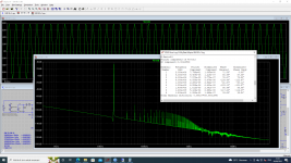
A solid state amplifier usually more higher frequency more bigger the THD.
So, I always check THD at 20kHz at low level and near clipping in my simulation.
So, I always check THD at 20kHz at low level and near clipping in my simulation.
My latest amplifier using PSU 90VDC. THD at 20kHz, 8 Ohm, 77V-peak only 0.000107%.A solid state amplifier usually more higher frequency more bigger the THD.
So, I always check THD at 20kHz at low level and near clipping in my simulation.
Attachments
A solid state amplifier usually more higher frequency more bigger the THD.
So, I always check THD at 20kHz at low level and near clipping in my simulation.
True, amplitude brings in another variable.
Indeed a full plot of harmonic distortion is four dimensional: fundamental input frequency, output waveform, amplitude of output waveform and amplifier level (gain).
That is interesting. I wonder why that is. I wonder as well what properties of a piece of equipment would make its even or odd harmonics higher.If the even harmonics peak higher than the odd (that is 2KHz and 4KHz etc are higher than 3KHz and 5KHz etc) then the amp is said to sound warm or pleasant. If the odd harmonics are higher, the amp is often described as clinical or harsh or sometimes unpleasant.
This is a generalisation and subject to eternal argument, but a basic understanding is the goal.
Also, does this even/odd harmonic balance rule of thumb about its translation to tonal quality apply to harmonic distortion in speaker drivers too? If so, would it be a good idea to choose drivers for multi way speakers that alternate between even and odd harmonic peaks to help avoid constructive interference, thus a presumably more audible harmonic? e.g. if you have a mid range that has higher odd harmonics, choose a tweeter with higher even harmonics?
In case this wasn't clear, I do not know much about audio 😛
That is interesting. I wonder why that is. I wonder as well what properties of a piece of equipment would make its even or odd harmonics higher.
Also, does this even/odd harmonic balance rule of thumb about its translation to tonal quality apply to harmonic distortion in speaker drivers too? If so, would it be a good idea to choose drivers for multi way speakers that alternate between even and odd harmonic peaks to help avoid constructive interference, thus a presumably more audible harmonic? e.g. if you have a mid range that has higher odd harmonics, choose a tweeter with higher even harmonics?
In case this wasn't clear, I do not know much about audio 😛
If you put a sine in to a box that distorts perfectly then if the distortion is:
Symetrical = odd harmonics
Asymetrical = even harmonics
It also depends not only on the component but the how the component reacts to the changing load behaviour.
A good example is a tube if you trace the input sine though a cycle, map to the output current with a constant resistive load line, the output will not be the sine wave in, but have distortion. That’s the simple way to demonstrate it.
Then it gets more complex with the schematic (typically push pull cancels out do you have even harmonics, SE doesnt cancel but that depends on if signal is fed back etc). Broskie’s akido design feeds power signal into cancel out.. so you can see it becomes complex if you get into details.
Loudspeakers, i suspect the same is true of reflected waves and materials not being perfect but distorting the relected/refracted signal.
Last edited:
The decades long electronic industry measured THD at one frequency at a time. 1kHz, 10kHz, 100Hz, etc.
If you want to measure another type of distortion, the decades long electronic industry measured Intermodulation distortion (IMD) of two separate frequency tones. Such as 250Hz and 8250Hz; or 11kHz and 12kHz, or other frequency tone pairs.
The 2nd order IM distortion products, and 3rd order IM distortion products are the ones most often considered and measured.
All decades old tests are subject to change, when someone decides to do that, but it does not change history.
More details of THD and IMD will not simplify the answer for the original poster.
Just my opinions
- Home
- Loudspeakers
- Multi-Way
- in layman's language, what is Total Harmonic Distortion