When you start adding all the parasitics to the simulation, you get an entirely different filter than you first expected.
No.The datasheet shows a value of 2.7 ohm being used but the optimum value would be different for different speakers. The aim of the Zobel is to make the amplifier see a consistent load impedance across the whole range of frequencies the particular speaker (usually the bass speaker) is designed to handle. Personally I have used a 4.7 Ohm (5 watt) resistor with good results.
The Speaker Zobel has a very different purpose to an Amplifier Output Zobel.
The Amplifier Output Zobel is there to help with ensuring stability and margins. This MUST be at the Amplifier Output AND it must have very low loop impedance to all the high frequencies (approaching and maybe even exceeding the low MegaHertz), that the amplifier can pass.
The Speaker Zobel is to help control the range of impedance seen by the Source feeding the speaker. This Source is often the crossover that expects to see a constant and fixed impedance to achieve the required roll-off and slope.
Last edited:
No.
The Speaker Zobel has a very different purpose to an Amplifier Output Zobel.
The Amplifier Output Zobel is there to help with ensuring stability and margins. This MUST be at the Amplifier Output AND it must have very low loop impedance to all the high frequencies (approaching and maybe even exceeding the low MegaHertz), that the amplifier can pass.
The Speaker Zobel is to help control the range of impedance seen by the Source feeding the speaker. This Source is often the crossover that expects to see a constant and fixed impedance to achieve the required roll-off and slope.
OK got it thanks for correcting the error.
The bypass capacitors are too small as mentioned by someone else I would recommend not 1000 but 10000 uf capacictors to lower the impedance of the power supply. They should be kept very close to the IC. After the 10000 uf capacitors you would need 0.1 uf disc ceramic capacitors very close to the power supply pins to stop any rf interference injecting into those pins.
You won't get much benefit (only a few mΩ) by increasing the bypass cap from 1000 µF to 10000 µF. The supply impedance near DC is dominated by the wiring connecting the main reservoir caps to the board.
You also won't get much benefit of the 100 nF ceramic. Bump it up to 1 uF or 4.7 uF X7R ceramic.
This is easy to confirm with A Simulation.
~Tom
Gootee has already shown us how well a 100nF x7r works in simulation, with the usual caveat to keep the loop area small.
I've shown that 100 nF X7R works in simulation too. I've also shown that 4.7 uF X7R works even better.
Neither Gootee nor I can change the laws of physics. It all boils down to lead inductance on the LM3886.
~Tom
Neither Gootee nor I can change the laws of physics. It all boils down to lead inductance on the LM3886.
~Tom
Especially if you use only one.I've also shown that 4.7 uF X7R works even better.
I'd go 4.7 uF X7R ceramic, 22 uF OSCON, 1000 uF electrolytic. You can see the link to my simulation result in post #165.
~Tom
~Tom
Hello,
Currently listening with LM3886 amplifier 20,000μF for each side in the psu.
The sound is very detailed, and have dark sound signature.
But the highs is not pleasant and the mids is laid back.
In summary the sound not "live" as the great LM1875.
Are there any recommendations how to improve the LM3886?
Schematic of amplifier:
An externally hosted image should be here but it was not working when we last tested it.
You need to either get rid of R2 since the volume pot is acting as the input impedence or place it before the 1K resistor as in it current place it is acting as a voltage divider. Also the volume pot should be 10K as National recommend a higher walue coupled with the capacitance between the wiper and the carbon tracks could be acting as a low pass filter which will cause a high frequency roll off. Also use a good quality pot if you can. I had this problem before with high frequency roll off because of the cheap pot I was using. If you have a function generator and oscilloscope you should check the audio band 20Hz - 20KHz is all there i.e. there is no attenuation.
Last edited:
Especially if you use only one.
Can you elaborate on that?
To quote Bruce Hofer from this month's audio.tst : The first rule in ultra-low distortion analog circuit design is to avoid non-inverting op-amp configurations like the plague.
All this stuff you guys are writing about caps and bypassing are of little consequence compared to changing the topology.
All this stuff you guys are writing about caps and bypassing are of little consequence compared to changing the topology.
Rather than relying on blanket statements, one can also analyze the system. One then realizes that the CM distortion in a non-inverting amp is a pretty high-order effect of little to no impact. One can then build both circuits and compare their distortions... I did that. The results are below. More detail in This Thread.
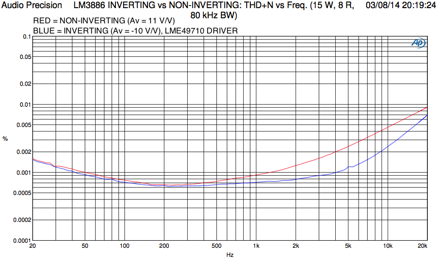
For a true apples-to-apples comparison, the gain of the two circuits should be the same. That puts the inverting amp at a slight disadvantage because it'll have slightly lower loop gain. I performed that experiment in a previous setup and found the inverting amp (Av = -11 V/V) to be nearly line-on-line with the non-inverting (Av = +11 V/V) amp as far as THD+N goes.
I really don't see any reason to avoid non-inverting op-amps "like the plague". In fact, you're more likely to screw up the performance implementing the drive circuitry needed to drive the low input impedance of the inverting amp.
~Tom
Last edited:
Tom,
did you do distortion measurement comparisons at gains of 2times and 20times?
Relating to 2times gains:
How do we compensate the two topologies to allow very low gains and still maintain the bandwidths and stability margins?
did you do distortion measurement comparisons at gains of 2times and 20times?
Relating to 2times gains:
How do we compensate the two topologies to allow very low gains and still maintain the bandwidths and stability margins?
Last edited:
On inverting and non-inverting op-amp configurations
I just received this today from Audio Precision:
NOTES FROM THE TEST BENCH
By Bruce Hofer
This month’s topic is common mode distortion in op-amps. The first rule in ultra-low distortion analog circuit design is to avoid non-inverting op-amp configurations like the plague. But why?
The answer lies in the variation in the complex input impedance seen at both the “+” and “-“ input pins of the op-amp in response to a common mode signal. The common mode impedance can be modeled as a parallel combination of a very high value resistor and a non-linear capacitor. In most well designed audio op-amps, the common mode resistance is usually so high that it will have a negligible effect. It is extremely high because the input differential pair is typically driven from a current source whose own output impedance is quite large. There is a slight non-linearity caused by base-width modulation in the current source, but that will not be covered here.
The effect of common mode capacitance is a very different story. Semi-conductor junction capacitance is a strong function of the reverse voltage appearing across the junction. As the reverse voltage across the junction increases, the junction capacitance decreases. This is true for both bipolar and JFET input stages. Unfortunately, JFET designs tend to have a higher junction capacitance, hence a higher common mode non-linearity. Certain design “tricks” can be applied inside the op-amp such as bootstrapping the input differential pair, but these usually cause an undesirable reduction in common mode range.
This is something the circuit designer can do to significantly reduce common mode distortion. If the rest of circuit can be made to present the same effective source impedance to both the “+” and “-“ inputs of the op-amp, common mode distortion due to non-linear input capacitance will cancel to the extent the impedances match. This usually involves the addition of a compensating impedance in series with either the “+” or “-“ input to balance the source impedances seen looking back out of the op-amp. In a simple voltage gain stage, this impedance can be as simple as a resistor. In active filter designs (e.g. Sallen and Key low pass filters) the impedance must be more complex, comprising multiple resistors and capacitors to equalize the source impedances at all frequencies within the band of interest.
Try it, you’ll like it! Analog designers are often surprised by the reduction in common mode distortion that can be achieved by the intelligent addition of a few passive components.
Enjoy this month’s edition of Audio.TST.
-Bruce Hofer
Audio Precision co-founder and Chief Analog Engineer
On a CMOS-input BiCMOS op-amp product (LMP8100 or LMP2021, I forget) I worked on quite a few years ago, I actually measured lower THD with the amp with it in a non-inverting buffer configuration. I rigged it as an inverting amp as well with a gain of -1. In that configuration, it had slightly higher THD.
My measurements above of the LM3886 (bipolar input) shows the inverting being marginally better. However, this does require a driver that can drive the low input impedance of the inverting configuration. This driver will need to be engineered and designed properly and its signal ground connected at the appropriate point in the LM3886 part of the circuit. Otherwise, the performance will be significantly worse than that of the LM3886 in non-inverting configuration.
That's why my recommendation is to use the non-inverting LM3886 unless you have test equipment to measure that you didn't screw up the grounding of the driver.
"Ground" sounds so simple in the textbook, but there are so many ways to screw it up...
~Tom
did you do distortion measurement comparisons at gains of 2times and 20times?
2x, no. 20x was slightly (negligibly) worse as you'd expect from the slightly lower loop gain.
Relating to 2times gains:
How do we compensate the two topologies to allow very low gains and still maintain the bandwidths and stability margins?
There are quite a few ways. I suggest looking at the chapter on stability (Ch 6 if memory serves) of Franco.
It's not super complicated, but it does help if you make a simple AC model of the LM3886 and the feedback network in some math software such as MATLAB/Octave/FREEMAT, or MathCad and work out the compensation there before transferring it into a circuit simulator and/or circuit for the final tweaks.
~Tom
Hofer's comment are for ultra low distortion ~ 1ppm or less, and common mode swing is bigger at low gains
audio power chip amps are not capable of ultra low distortion on their own, and most are decompensated for Av >10 - so they don't have much common mode on the input even in noninverting mode
inverting is not a panacea, power chip amps are limited by many other errors than common mode input nonlinearity
Last edited:
does the 6dB gap/difference in distortion around the 4kHz to 8kHz frequencies reduce?............. 20x was slightly (negligibly) worse as you'd expect from the slightly lower loop gain.
I won't be spending $212.48, even with free postage to find out.There are quite a few ways. I suggest looking at the chapter on stability (Ch 6 if memory serves) of ..............Franco............
I have tried googling with lot's of search criteria and found little of any use.
I am in the middle of adding 3886 amps to active desktop monitors, but there is too much noise and I would like to try 10times gain but maintain the margins that exist with 28times gain.
Last edited:
That's easy, 'Noise Gain Compensation' is the google keyword -- a series RC between + and - input pins. Can be done for inverting and non-inverting (note that in the latter case you also need a low/known impedance drive and never leave the input open).I am in the middle of adding 3886 amps to active desktop monitors, but there is too much noise and I would like to try 10times gain but maintain the margins that exist with 28times gain.
- Status
- Not open for further replies.
- Home
- Amplifiers
- Chip Amps
- Improving the LM3886 amplifier