metalman said:
Previous discussion answered pretty much everything, but I thought I'd add the comment that with feedback taken after the 10uF output caps, and the preamp driving a 3K load, at 20Hz the circuit is only down 0.0017dB with less than 1.5� phase shift. 5� phase shift occurs at 4.6Hz where it is down 0.0325dB.
The point of this is that the lower pole isn't having any significant consequence in the audio band with the feedback taken after the cap, you avoid the DC feedback issue, and you allow any non-linearities from the cap to be included in the both the normal and supersymmetry feedback signals.
Terry
Thanks Terry,
Yes after a couple of responses and some thinking I can see now there is a lot of value to the approach. 🙂
Cheers!
Russ
If we're going to give it a good rework, may I suggest considering an upgraded CCS such as the one from Figure 9F of Walt Jungs recent AudioXpress article: Sources 101: Audio Current Regulator Tests for High Performance, Part 1 Basics of Operation.
Better than 120dB noise rejection across the audio band!
Terry
P.S. a J507 is a possible substituted for the J113.
Better than 120dB noise rejection across the audio band!
Terry
P.S. a J507 is a possible substituted for the J113.
Attachments
Re: Lotus.?.?.?
I have re-established the Balanced output of the J-fet-BosoZ and has been listening to it on my A-X's for a couple of hours. Man, I cant recognize my BosoZ anymore! It sounds totally different. A lot more topend heavy. Not that it lacks bottom, but the topend is a lot different! I think its more stretched out and detailed, and the soundstage is wider and deeper. BTW I have an easier time comparing the stock Twisted to the Jfet Twisted, when using the A-X's, simply because thats where I use the Twisted BosoZ every day! The A-X's gained some of the terrain, first lost to the F4! No doubt about that fact. But the overall sound is a lot different. I am not sure if some distortion is at play, BUT to me it sounds a bit coloured! I didnt hear that on the F4. Any ideas are welcomed.
Steen🙂
Lotus sounds cool, but to avoid any misunderstandings, what about "Bride of F4" , doesnt sound catchy at all, but it would avoid most..... well you know....🙂 Unless Mr. Pass had his mind set on the name ofcourse, for any future preamp?Russ White said:Trying to come up with a name for this pre that is not some long chain of Xs ,Ss, and Cs etc.... 🙂
So I thought Lotus might be cool.
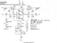
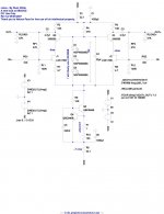
Anyway here is my first take. It simulates very well. and should be able to swing about 45VPP with 60V at VDD. This should drive F4 very well. 🙂
Here it is. Feedback appreciated.
Cheers!
Russ

I have re-established the Balanced output of the J-fet-BosoZ and has been listening to it on my A-X's for a couple of hours. Man, I cant recognize my BosoZ anymore! It sounds totally different. A lot more topend heavy. Not that it lacks bottom, but the topend is a lot different! I think its more stretched out and detailed, and the soundstage is wider and deeper. BTW I have an easier time comparing the stock Twisted to the Jfet Twisted, when using the A-X's, simply because thats where I use the Twisted BosoZ every day! The A-X's gained some of the terrain, first lost to the F4! No doubt about that fact. But the overall sound is a lot different. I am not sure if some distortion is at play, BUT to me it sounds a bit coloured! I didnt hear that on the F4. Any ideas are welcomed.
Steen🙂
Not to complicate matters, but don't assume that better specs translate to a better sounding current source. I've seen the Jung article and can say that I've tried a number of those current sources. The ones that measure better are not necessarily the ones that sound better.
Grey
Grey
metalman said:
Previous discussion answered pretty much everything, but I thought I'd add the comment that with feedback taken after the 10uF output caps, and the preamp driving a 3K load, at 20Hz the circuit is only down 0.0017dB with less than 1.5� phase shift. 5� phase shift occurs at 4.6Hz where it is down 0.0325dB.
The point of this is that the lower pole isn't having any significant consequence in the audio band with the feedback taken after the cap, you avoid the DC feedback issue, and you allow any non-linearities from the cap to be included in the both the normal and supersymmetry feedback signals.
Terry

OK I have been working some more on this here are my ideas:
I would like to use dual transistors all devices.
For CCS and Cascodes:
BC846B
http://www.onsemi.com/pub/Collateral/BC846BDW1T1-D.PDF
For the JFET pair:
LSK389B
http://www.linearsystems.com/datasheets/LSK389.pdf
This should give excellent thermal tracking between devices and provide close tolerance for the JFETs.
It will also make for a nice compact layout.
None of the active components dissipate more than 200mw each 400mw combined for the cascodes. Those I may need to use single device packages do to thermal conciderations... Not sure.
Here is the simulated distortion at 20khz 4Vpp.
Harmonic Frequency Fourier Normalized Phase Normalized
Number [Hz] Component Component [degree] Phase [deg]
1 5.000e+03 4.356e+00 1.000e+00 -0.05° 0.00°
2 1.000e+04 7.539e-08 1.730e-08 91.62° 91.67°
3 1.500e+04 5.269e-05 1.209e-05 1.97° 2.02°
4 2.000e+04 5.979e-10 1.372e-10 101.77° 101.83°
5 2.500e+04 3.884e-08 8.916e-09 -178.54° -178.49°
6 3.000e+04 1.119e-09 2.569e-10 35.65° 35.70°
7 3.500e+04 1.916e-09 4.398e-10 -43.82° -43.77°
8 4.000e+04 3.270e-10 7.505e-11 -64.78° -64.73°
9 4.500e+04 1.051e-09 2.413e-10 141.68° 141.73°
Total Harmonic Distortion: 0.001209%
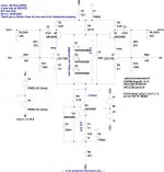
Attached is the output impedance graph...
Notice it is now down to about 225R
I would like to use dual transistors all devices.
For CCS and Cascodes:
BC846B
http://www.onsemi.com/pub/Collateral/BC846BDW1T1-D.PDF
For the JFET pair:
LSK389B
http://www.linearsystems.com/datasheets/LSK389.pdf
This should give excellent thermal tracking between devices and provide close tolerance for the JFETs.
It will also make for a nice compact layout.
None of the active components dissipate more than 200mw each 400mw combined for the cascodes. Those I may need to use single device packages do to thermal conciderations... Not sure.
Here is the simulated distortion at 20khz 4Vpp.
Harmonic Frequency Fourier Normalized Phase Normalized
Number [Hz] Component Component [degree] Phase [deg]
1 5.000e+03 4.356e+00 1.000e+00 -0.05° 0.00°
2 1.000e+04 7.539e-08 1.730e-08 91.62° 91.67°
3 1.500e+04 5.269e-05 1.209e-05 1.97° 2.02°
4 2.000e+04 5.979e-10 1.372e-10 101.77° 101.83°
5 2.500e+04 3.884e-08 8.916e-09 -178.54° -178.49°
6 3.000e+04 1.119e-09 2.569e-10 35.65° 35.70°
7 3.500e+04 1.916e-09 4.398e-10 -43.82° -43.77°
8 4.000e+04 3.270e-10 7.505e-11 -64.78° -64.73°
9 4.500e+04 1.051e-09 2.413e-10 141.68° 141.73°
Total Harmonic Distortion: 0.001209%
Attached is the output impedance graph...
Notice it is now down to about 225R
Attachments

Russ White said:
Notice it is now down to about 225R
Excellent work Russ
That sounds great to me, non the less, it is time to test it soundwise.
Maybe Steen is the guinea pig 😀
Russ White said:............
None of the active components dissipate more than 200mw each 400mw combined for the cascodes. Those I may need to use single device packages do to thermal conciderations... Not sure.
...........
those little bjts will cook with 400mW combined
Zen Mod said:
those little bjts will cook with 400mW combined
Yes once I got a good look at the datasheet I see that. I will probably use two BC546C TO-92 types. They should handle 200mw each fine right?
Russ White said:
Yes once I got a good look at the datasheet I see that. I will probably use two BC546C TO-92 types. They should handle 200mw each fine right?
yup
decrease current through halves to ~ 7mA.........jfets will be further from sat. , cascodes will be slightly relaxed
I overlooked - what are PS voltages?
Attachments
Re: Re: Lotus.?.?.?
I think it's due to the fuction of total gain and distortion.
The gain of pre+F4 depends on the pre amp gain alone
while the gain of pre+AX is pre gain times power amp gain.
I guess that your description of top end sound means
that the top end is too much and out of tone-balance.
I usually try to get normal listening level at about 10-11
o'clock volume knob, saving total gain at proper level ^^;

steenoe said:I have re-established the Balanced output of the J-fet-BosoZ and has been listening to it on my A-X's for a couple of hours. Man, I cant recognize my BosoZ anymore! It sounds totally different. A lot more topend heavy. Not that it lacks bottom, but the topend is a lot different! I think its more stretched out and detailed, and the soundstage is wider and deeper. BTW I have an easier time comparing the stock Twisted to the Jfet Twisted, when using the A-X's, simply because thats where I use the Twisted BosoZ every day! The A-X's gained some of the terrain, first lost to the F4! No doubt about that fact. But the overall sound is a lot different. I not sure if some distortion is at play, BUT to me it sounds a bit coloured! I didnt hear that on the F4. Any ideas are welcomed.
Steen🙂
I think it's due to the fuction of total gain and distortion.
The gain of pre+F4 depends on the pre amp gain alone
while the gain of pre+AX is pre gain times power amp gain.
I guess that your description of top end sound means
that the top end is too much and out of tone-balance.
I usually try to get normal listening level at about 10-11
o'clock volume knob, saving total gain at proper level ^^;
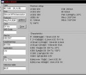
OK so this whole JFET deal is a bit new to me.
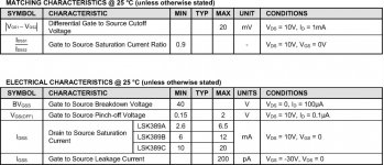
Looking at the datasheet for the LSK389 I see that the "B" version has a minimum saturation current of 6ma and a max of 12ma.
Thats quite a range.
I guess I have to plan for the worst?
I suppose I should probably aim for just over half the lowest possible sat current which would be 6ma. So 3ma bias current? or should I go up a bit say to 4ma and hope that I don't saturate?
What happens if I do hit the saturation current? (don't really see much in the sim, might not be modeled)
Anyway, Maybe something like this?
Attachments
Russ White said:OK so this whole JFET deal is a bit new to me.
Looking at the datasheet for the LSK389 I see that the "B" version has a minimum saturation current of 6ma and a max of 12ma.
Thats quite a range.
I guess I have to plan for the worst?
I suppose I should probably aim for just over half the lowest possible sat current which would be 6ma. So 3ma bias current? or should I go up a bit say to 4ma and hope that I don't saturate?
What happens if I do hit the saturation current? (don't really see much in the sim, might not be modeled)
Anyway, Maybe something like this?
OK...........choose middle of working region............that means 9mA per jfet.........
3mA is waaaaay too low
when you hit sat current.............clipping
Ok now I really need to sort this out... 🙂
It would seem to me I should keep the JFETs operation in their linear region, right? with the "B" part 6ma could be in the saturation region. So it would seem to me I would want 3ma for the "B" part or 5ma for the "C" part.
I would not want to operate them in saturation right?
Here is from the datasheet:
Attachments
Does anyone have an opinion of using the dual 389 vs two 170s?
Benefits of the 389 are better thermal coupling and claimed better matching (likely). Benefit of 170's is that you can use original 2SK170B or the LSK170B.
Thoughts?
Benefits of the 389 are better thermal coupling and claimed better matching (likely). Benefit of 170's is that you can use original 2SK170B or the LSK170B.
Thoughts?
Russ White said:Ok now I really need to sort this out... 🙂
It would seem to me I should keep the JFETs operation in their linear region, right? with the "B" part 6ma could be in the saturation region. So it would seem to me I would want 3ma for the "B" part or 5ma for the "C" part.
I would not want to operate them in saturation right?
Here is from the datasheet:
without exact selecting it's hard to tell where little jfet will go nutz........but in real world that's not that complicated and serious;
to be sure 158% ,just place trimpot where it belongs - in CCSink and everything is OK ; instead resistor only,put combo resistor+pot,covering typical range of 5 to 12 mA and everything is OK
there is no need to over-engineering here
- Status
- Not open for further replies.
- Home
- Amplifiers
- Pass Labs
- Improving on X-BosoZ to mate the F4