Oh Steenoe, pretty please with ice-cream on top, could you enlighten us?🙂  😀
😀
And where do we get those lovely jfets?
😀And where do we get those lovely jfets?
BrianDonegan said:From the pic alone, I have this. Need to re-read for R values.
Hi Brian,
Weren't there changes to the power supply?
Okay.
From Choky and Terry, I have these R changes:
- The new R's on the JFet pins are 10R.
- R18, R19 change from 39K to 100K.
- R1, R2, R6, R7 change from 1.5K (2 in parl for 750R) to 6K (two in parl for 3K). Kit will probably keep them as 3W Pannies to live a long life, but may switch to a single 3K 3W.
Other thoughts on new boards:
- will support both FET and JFet front end
- Make the R spacing a bit larger for the Dale RN60s and make them kit standard
- 5mm pads for the 220nf caps (thinking AVX stacked film (MKT), but can find MKP as well).
- Thinking about Wima MKP4 for C4 and C5, perhaps 10uF 250V 5%, but maybe even 4.7uF to keep costs resonable. Will keep multi pads for these
- Switch to single 10V VRef/R/Cap
Ampslab seems to have stock of the 2SK170BL, but also looking at Linear LSK170B. Thought on that? I am waiting for a price quote. Could also use LSK389 dual to make matching easier (no source yet for lots of 2SK389)...
For power supply, we would probably just use our TXPS boards (zener follower reg).
BrianDonegan said:
Ampslab seems to have stock of the 2SK170BL, but also looking at Linear LSK170B. Thought on that? I am waiting for a price quote. Could also use LSK389 dual to make matching easier (no source yet for lots of 2SK389)...
BTW, I just received 20 2SK170BL's from Ampslab and a half dozen LSK389BL's (2SK389) from LinearSystems. The sales rep at LinearSystems is open to a volume pricing deal with a member of this forum for us DIYer's.
-David
carpenter said:Weren't there changes to the power supply?
Nope, power supply is left as is.
BrianDonegan said:R18, R19 change from 39K to 100K?
Just want to note that this change was to raise the circuit gain to 20dB for adequate drive with an F4. For other amps, the 39K for 12dB gain will be fine.
Terry
Just want to note that this change was to raise the circuit gain to 20dB for adequate drive with an F4. For other amps, the 39K for 12dB gain will be fine.
Cool. I can include both R sets with appropriate labels (have lots of Dales left over fromt he first run, and 100Ks are used elsewhere, so I have them).
The sales rep at LinearSystems is open to a volume pricing deal with a member of this forum for us DIYer's.
Since they are harder to buy, I was thinking of stocking some as well. I have not, as yet, seen any comment or direct comparison with the Toshibas. That would be good.
JFET'S suitability
I have 4 LSK389 at the "A" level (2-6.5 ma) .Will they work in this circuit??
dw8083 said:
BTW, I just received 20 2SK170BL's from Ampslab and a half dozen LSK389BL's (2SK389) from LinearSystems. The sales rep at LinearSystems is open to a volume pricing deal with a member of this forum for us DIYer's.
-David
I have 4 LSK389 at the "A" level (2-6.5 ma) .Will they work in this circuit??
Re: JFET'S suitability
I have doubts that IRF in cascodes can bread on just 5mA;
too wimpy,even 10 mA in last "Jfet XCCSED!@#$%^&***%$#WTFBOSOZ" is on wimpy side......at least to my taste.....
anyway-also for my taste- that preamp is just transition point to something really better ;
2SKs with bjts as cascodes looks something less compromised to me than 2SKs with IRFs.........reasons explained above
sandstorm33 said:
I have 4 LSK389 at the "A" level (2-6.5 ma) .Will they work in this circuit??
I have doubts that IRF in cascodes can bread on just 5mA;
too wimpy,even 10 mA in last "Jfet XCCSED!@#$%^&***%$#WTFBOSOZ" is on wimpy side......at least to my taste.....
anyway-also for my taste- that preamp is just transition point to something really better ;
2SKs with bjts as cascodes looks something less compromised to me than 2SKs with IRFs.........reasons explained above
Are you guys infected with the J-fet fever? Terrible disease.
You are doomed to search the world for those little critters for the rest of your life🙂
For you guys over there in the states, this is the only source for the Toshiba's I know of over there: http://www.tech-diy.com/smallsignal.htm Its the DIYaudio user Jackinnj's shop. My beleive is that there is plenty, and luckily he has both the P-channels and the N-channels. Dont forget to order the
2SJ74's for the F4 also, while you are at it😉 A dozen or two of each, will go a long way. I dont think more pics are needed, the only visible difference from the old BosoZ is the 2 J-fets you saw on the earlier pic I posted. Its very easy to implement the J-fet modification on the Twisted BosoZ if you have a kit of those. Only little trouble is that you have to twist 2 legs and add a source resistor to the third, but you saw that on the pic mentioned. Just check the datasheets for pinouts.
Really a nice little mod with a great outcome.
Steen🙂
BTW
Dont wait for the next amp-design, from here on there is only one way........
😀
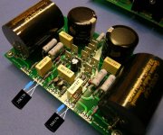
Edit Here is the pic. Notice how the J-fets are waving at you in the most inviting way 😉
J-fet modification.
You are doomed to search the world for those little critters for the rest of your life🙂
For you guys over there in the states, this is the only source for the Toshiba's I know of over there: http://www.tech-diy.com/smallsignal.htm Its the DIYaudio user Jackinnj's shop. My beleive is that there is plenty, and luckily he has both the P-channels and the N-channels. Dont forget to order the
2SJ74's for the F4 also, while you are at it😉 A dozen or two of each, will go a long way. I dont think more pics are needed, the only visible difference from the old BosoZ is the 2 J-fets you saw on the earlier pic I posted. Its very easy to implement the J-fet modification on the Twisted BosoZ if you have a kit of those. Only little trouble is that you have to twist 2 legs and add a source resistor to the third, but you saw that on the pic mentioned. Just check the datasheets for pinouts.
Really a nice little mod with a great outcome.
Steen🙂
BTW
Dont wait for the next amp-design, from here on there is only one way........
😀
Edit Here is the pic. Notice how the J-fets are waving at you in the most inviting way 😉
J-fet modification.
Re: Re: JFET'S suitability
breathe ........of course,not bread

Zen Mod said:
I have doubts that IRF in cascodes can bread on just 5mA;
.........
breathe ........of course,not bread
steenoe said:................
Edit Here is the pic. Notice how the J-fets are waving at you in the most inviting way 😉
J-fet modification.
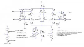
btw-here is definitive schematic.......it will be there for good 😉
http://tiny.pl/dj2t
look for "Jfet cascoded CCS-ed BOSOZ for Steenoe"
Thats great🙂 I see more interesting things.....look for "Jfet cascoded CCS-ed BOSOZ for Steenoe"
Yep, ear-friendly😉They DO seem to be friendly critters
Steen🙂
steenoe said:Edit Here is the pic. Notice how the J-fets are waving at you in the most inviting way 😉
J-fet modification.
Thanks for the picture, Steen.
By the way, are they Toshiba 2SK170's?
Toshiba's spec says height 4.7mm max and width 5.1mm max.

Russ White said:How far off does something like this look?
Why . . .
Taking FB before cap . . . ?
Then, also need to put additional cap behind R16,
and adjust R5, R14 and R18 sizes.
Babowana said:
Why . . .
Taking FB before cap . . . ?
Then, also need to put additional cap behind R16,
and adjust R5, R14 and R18 sizes.
Just an experiment. Was not sure if it was a good idea....
Russ White said:Ok I am simulating a couple options. 🙂
How far off does something like this look?
:EDIT: changed back some values I was testing in simulation:EDIT:
take feedback from outputs-after caps
toss out C6......
decrease R9 to 100E and put trimpot 47E in line or-even better- use two bjt CCSink
use something as BC546C instead 5550 in cascodes
take all this with salt........

Russ White said:Ok I am simulating a couple options. 🙂
How far off does something like this look?
Nice iteration...
Needs a cap to grd after R1, no need for C2.
VSS would need a similar treatment as VDD, like a R1 plus the missing cap.
- Status
- Not open for further replies.
- Home
- Amplifiers
- Pass Labs
- Improving on X-BosoZ to mate the F4