Thanks for the feedback guys,
Speaking of feedback, I am struggling (please be kind) as to why I should take the feedback after the cap. It would seem to me that would introduce a couple of undesirable things. For one you now have a filter based on the input impedance of the power amp and the cap which will act to lower feedback to the preamp of low frequencies.
What is the downside to taking the feedback before the cap? Is it that there will be some offset at the inputs?
Cheers!
Russ
Russ White said:.............
What is the downside to taking the feedback before the cap? Is it that there will be some offset at the inputs?
Cheers!
Russ
yes......introducing DC from output to input
take feedback from output cap side.
besides---------easy bet--------- increase somewhat R9......goal is to have ~7 to 8mA through each 2SK170.........with 10mA asymetrical clipping is near
Zen Mod said:
yes......introducing DC from output to input
take feedback from output cap side.
besides---------easy bet--------- increase somewhat R9......goal is to have ~7 to 8mA through each 2SK170.........with 10mA asymetrical clipping is near
Thanks,
OK so the compromise is that we now have a pole on the feedback loop which means that gain increases toward DC? So we sacrifice linearity for null offset?
Cheers!
Russ
Russ White said:
Thanks,
OK so the compromise is that we now have a pole on the feedback loop which mean that gain increases toward DC? So we sacrifice linearity for null offset?
Cheers!
Russ
original XCCSWhatever BOSOZ was made like this,and nobody argue 😉
besides , feedback resistor is - what-47K,100K........where is it with 4U7.... 0,7Hz......................
**** sims........just build it and test
Zen Mod said:
original XCCSWhatever BOSOZ was made like this,and nobody argue 😉
besides , feedback resistor is - what-47K,100K........where is it with 4U7.... 0,7Hz......................
**** sims........just build it and test
But you have to factor in the load. Which could be significantly lower than 47K.
I am just seeking to understand. 🙂
Russ White said:Thanks for the feedback guys,
Speaking of feedback, I am struggling (please be kind) as to why I should take the feedback after the cap. It would seem to me that would introduce a couple of undesirable things. For one you now have a filter based on the input impedance of the power amp and the cap which will act to lower feedback to the preamp of low frequencies.
What is the downside to taking the feedback before the cap? Is it that there will be some offset at the inputs?
Cheers!
Russ
As Choky sez, you will bias the input gate at a different DC voltage other than grd potential.
Besides, as a plus you will include the non liniarity of the output cap to the FB... thats nice to have.
🙂
apassgear said:
As Choky sez, you will bias the input gate at a different DC voltage other than grd potential.
Besides, as a plus you will include the non liniarity of the output cap to the FB... thats nice to have.
🙂
Ah yes, that actually does seem helpful.
Thanks for the mental kick start.
Next wild question...
Why not exchange R5/R6 for active loads?
If one wanted to do that are there examples?
Why not exchange R5/R6 for active loads?
If one wanted to do that are there examples?
Russ White said:Next wild question...
Why not exchange R5/R6 for active loads?
If one wanted to do that are there examples?
http://choky.on.neobee.net/My various musings from Diyaudio.html
"Jfet BOSOZ. Not tested"
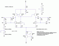
Russ White said:What about something like this?
CCSink is OK with me-same as chosen current (~7mA) ;
but- cascodes are here of more benefit than current mirror .
anyway-without much analyzing, I think that is best to bring back cascodes,along with plain resistors as load.
all magic is in tail here .
in layout-keep Q5 and Q6 together ; also replace R12 with resistor-trimpot string,even if that isn't necessary
ZM blah blah....... 😉
edit:
thread is just splitted.... I was hysteric for moment....looking at topic and slightly recognizing anything 😉
to repeat my self.......all magic is in tail here ,SUSY, balance ,everything.
seems that I remember Gray pointed numerous times that resistors often works better than various CCSes as load......that's exactly my xperience with toob circs ; even if just introduced CCS load sounds somewhat more atractive,not just once I rolled it back to plain resistor.....but with carefully chosen value......
I see no reason why that can't be case here.......simple circ,and elegant. keeping it in reasonable boundaries is must .....hehe.......loading impedance is critical too......
Thx Choky,
I agree with you, in this case simple is probably best.
I will post my changes soon.
BTW that circuit above was just meant to demonstrate the active load, It was not complete.
Cheers!
Russ
I agree with you, in this case simple is probably best.
I will post my changes soon.
BTW that circuit above was just meant to demonstrate the active load, It was not complete.
Cheers!
Russ
Lotus.?.?.?
Trying to come up with a name for this pre that is not some long chain of Xs ,Ss, and Cs etc.... 🙂
So I thought Lotus might be cool.
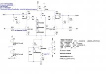
Anyway here is my first take. It simulates very well. and should be able to swing about 45VPP with 60V at VDD. This should drive F4 very well. 🙂
Here it is. Feedback appreciated.
Cheers!
Russ
Trying to come up with a name for this pre that is not some long chain of Xs ,Ss, and Cs etc.... 🙂
So I thought Lotus might be cool.
Anyway here is my first take. It simulates very well. and should be able to swing about 45VPP with 60V at VDD. This should drive F4 very well. 🙂
Here it is. Feedback appreciated.
Cheers!
Russ
Attachments

Re: Lotus.?.?.?
in real life try to use something bigger voltage for jfets ( few more leds in cascode leveling)
somewhat smaller source degeneration........10,22,39 ohms
two BJT CCSink.......(better tempco)
BCxxxC suffix........(I know....blame models 😉 )
middle of current range for chosen jfet ( on top of my head -current looks somewhat smaller........calc also for cascode leveler current)
and-what' simmed output impedance?
Russ White said:Trying to come up with a name for this pre that is not some long chain of Xs ,Ss, and Cs etc.... 🙂
So I thought Lotus might be cool.
Anyway here is my first take. It simulates very well. and should be able to swing about 45VPP with 60V at VDD. This should drive F4 very well. 🙂
Here it is. Feedback appreciated.
Cheers!
Russ
in real life try to use something bigger voltage for jfets ( few more leds in cascode leveling)
somewhat smaller source degeneration........10,22,39 ohms
two BJT CCSink.......(better tempco)
BCxxxC suffix........(I know....blame models 😉 )
middle of current range for chosen jfet ( on top of my head -current looks somewhat smaller........calc also for cascode leveler current)
and-what' simmed output impedance?
Very nice circuit!
How much input voltage will it accept? I see the LSK data sheets list Vgs off min as .2 V, and max as 2V -- so won't a typical CD output need to be attenuated by at least half at the input? (if you find a bunch of Vgs off = 2V jfets...)
JJ
How much input voltage will it accept? I see the LSK data sheets list Vgs off min as .2 V, and max as 2V -- so won't a typical CD output need to be attenuated by at least half at the input? (if you find a bunch of Vgs off = 2V jfets...)
JJ
Originally posted by Russ White
OK so the compromise is that we now have a pole on the feedback loop which means that gain increases toward DC? So we sacrifice linearity for null offset?
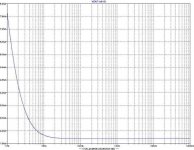
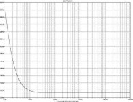
Previous discussion answered pretty much everything, but I thought I'd add the comment that with feedback taken after the 10uF output caps, and the preamp driving a 3K load, at 20Hz the circuit is only down 0.0017dB with less than 1.5° phase shift. 5° phase shift occurs at 4.6Hz where it is down 0.0325dB.
The point of this is that the lower pole isn't having any significant consequence in the audio band with the feedback taken after the cap, you avoid the DC feedback issue, and you allow any non-linearities from the cap to be included in the both the normal and supersymmetry feedback signals.
Terry
- Status
- Not open for further replies.
- Home
- Amplifiers
- Pass Labs
- Improving on X-BosoZ to mate the F4