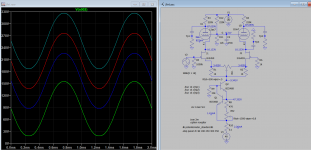
Yesterday I played a bit with LTSpice and different values of CSS together with different plate resistors. I will report here some results with currents above 1 mA. I've found some sweet spots (again, based on models) where, without gnfb, there's very low THD and it's mainly 3rd harmonic.
Of course, the higher the current, the lower the plate resistors, so the lower the gain of the PI. I need to check what will be the acceptable limit with my DAC.
Of course, the higher the current, the lower the plate resistors, so the lower the gain of the PI. I need to check what will be the acceptable limit with my DAC.
Bob Pease talked about simulations in his EDN magazine column, "Pease Porridge".
He was a very intelligent fellow. Some of you remember his statements about the limits of simulations.
Boeing used simulations.
There is no comparison between those two statements, but perhaps there are some hidden lessons there.
He was a very intelligent fellow. Some of you remember his statements about the limits of simulations.
Boeing used simulations.
There is no comparison between those two statements, but perhaps there are some hidden lessons there.
Hi 6A3sUMMER,
I know I know, models are far from representing reality, most of the time due to who's in front of the computer that is simulating.
For me it's just a way to come closer to the final solution, and understand how things correlate. Then I know there's need to hear and modify "on the fly".
I've some guitar amp design in my past, and I always used sims to find different approaches, but never went closer to the final solution with sims.
Here I used just to find some starting points of combos current & plate resistors that then I'll investigate further.
Did you mean to connect the grids of U1 U2 back to the plates. I would think that the grids just need to be a fraction of the HT supply.
No, U1 and U2’s grids are set by the voltage divider at 1/10th of the supply circa.
I mean that the 220 kOhm of the original design will need to decrease in value when the CCS current goes up.
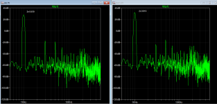
Yesterday I’ve found some useful combination, and two of them were with 3rd harmonic “only” (others were at least one to two orders of magnitude lower).
I mean that the 220 kOhm of the original design will need to decrease in value when the CCS current goes up.
Yesterday I’ve found some useful combination, and two of them were with 3rd harmonic “only” (others were at least one to two orders of magnitude lower).
Hi,
Which schematic you're simulating? Another way is to vary the plate supply voltage, say from 180v to 350v, the DC to next stage can be varies from 90v to 250v while the output level and distortion remained the same. This happens due the constant current source.
Which schematic you're simulating? Another way is to vary the plate supply voltage, say from 180v to 350v, the DC to next stage can be varies from 90v to 250v while the output level and distortion remained the same. This happens due the constant current source.
Attachments
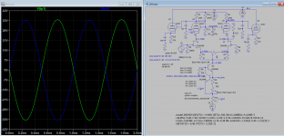
Thanks for the simulation Koonw, I'm simulating the full schematic, so yours plus the driver and the power amp with EL34, 430VB+, 7kRaa, 43%v DL, cathode feedback grounding the 4 Ohm secondary tap and using the 0 and 16 Ohm taps.
This is how it is now. I'm trying without gnfb by now, trying to improve it that way, then implement gnfb later.
This is how it is now. I'm trying without gnfb by now, trying to improve it that way, then implement gnfb later.
One problem with ltspice is everything is nicely matched. Its worth try two JETs that are slightly different and one tube slightly different from the 12ax7 to see how it behaves. That will give some second harmonic.
This is the model I used, it is easy to change the param but which one is most likely to vary?
Code:
.model 2N5459 NJF(VTO=-4.4691 BETA=377.39e-6 LAMBDA=4.1648E-3
+ALPHA=5.0E-7 VK=30 RD=1.0 RS=1.0 N=1.0 IS=4.0937e-15 ISR=8.7937e-13
+CGD=5.8248E-12 CGS=3.8836E-12 M=0.38 PB=0.664 KF=1.3542E-6 AF=1.9123E-3
+BETATCE=-0.46 VTOTC=-2.50E-3)Rather than do that pick another JFET which is very similar. I`ve used J111-J113 before which gives you a spread to see what happens. Or use one as a 2N5458. You may well need a matched pair anyway. It will give you a feel for tolerances.
Last edited:
2N3819 can be used as another pairs amid higher gain than 2n5459, but can't be used with 2n3819. need to use FFT to see the harmonics details though. 2N3819 is cheap and more common.
Can it be a good approximation unbalancing the balance trimmer, instead of changing the fet/triode characteristics?
OK the idea is to see if you can rebalance a slightly mismatched set of FETs to see what the impact may be.
*
* 2N5458 N−Channel JFET
*
* From http://www.gunthard-kraus.de/Spice_Model_CD/Vendor%20List/Spice-Models-collection/jfet.lib
*
2n5459/5458, I can't balance them, you can try.
* 2N5458 N−Channel JFET
*
* From http://www.gunthard-kraus.de/Spice_Model_CD/Vendor%20List/Spice-Models-collection/jfet.lib
*
Code:
.model J2N5458    NJF(Vto=-2.882 Beta=488.9u Lambda=3.167m Rd=1 Rs=1 Cgs=4.627p
  +Cgd=4p Pb=.5 Is=181.3f Kf=4.284E-18 Af=1 Fc=.5)
Last edited:
Is a pairs, not mixed. The full range of variable pot will adjust is 0.1V (say 2.383v to 2.496v) on drain.Just to check that was with the left fet 2n3819 and the right fet 2n5419.
Last edited:

I report here some simulation results of the complete amp (without gnfb) at 8 Ohm secondary tap and 30 Wrms:
1 mA (Rcss = 1k5) and 82k on PI's plates:
0,9 mA (Rcss = 1k7) and 100k on PI's plates:
0,6 mA (Rcss = 2k5) and 150k on PI's plates:
0,4 mA (Rcss = 3k6) and 220k on PI's plates:
0,35 mA (Rcss = 4k5) and 270k on PI's plates:
1,5mA (Rcss = 1k) and 150k on PI's plates (220k-12k voltage divider for 12ax7's grids):
1 mA (Rcss = 1k5) and 82k on PI's plates:
Code:
Harmonic	Frequency	 Fourier 	Normalized	 Phase  	Normalized
 Number 	  [Hz]   	Component	 Component	[degree]	Phase [deg]
    1   	1.000e+03	2.216e+01	1.000e+00	   -1.29°	    0.00°
    2   	2.000e+03	6.006e-03	2.710e-04	 -158.89°	 -157.60°
    3   	3.000e+03	4.217e-02	1.903e-03	    8.85°	   10.14°
    4   	4.000e+03	4.563e-03	2.059e-04	  127.47°	  128.75°
    5   	5.000e+03	4.114e-02	1.857e-03	  177.76°	  179.05°
    6   	6.000e+03	2.593e-03	1.170e-04	 -138.99°	 -137.70°
    7   	7.000e+03	1.281e-02	5.780e-04	   -3.67°	   -2.38°
    8   	8.000e+03	1.484e-03	6.695e-05	  156.60°	  157.89°
    9   	9.000e+03	5.954e-03	2.687e-04	  175.28°	  176.56°
Total Harmonic Distortion: 0.275825%(0.276304%)
0,9 mA (Rcss = 1k7) and 100k on PI's plates:
Code:
Harmonic	Frequency	 Fourier 	Normalized	 Phase  	Normalized
 Number 	  [Hz]   	Component	 Component	[degree]	Phase [deg]
    1   	1.000e+03	2.241e+01	1.000e+00	   -1.31°	    0.00°
    2   	2.000e+03	6.589e-03	2.940e-04	 -149.69°	 -148.38°
    3   	3.000e+03	4.217e-02	1.882e-03	    9.26°	   10.57°
    4   	4.000e+03	5.157e-03	2.301e-04	  122.49°	  123.80°
    5   	5.000e+03	4.786e-02	2.136e-03	  177.61°	  178.92°
    6   	6.000e+03	2.871e-03	1.281e-04	 -134.36°	 -133.05°
    7   	7.000e+03	1.547e-02	6.904e-04	   -4.10°	   -2.80°
    8   	8.000e+03	1.530e-03	6.825e-05	  152.16°	  153.47°
    9   	9.000e+03	6.888e-03	3.074e-04	  174.33°	  175.64°
Total Harmonic Distortion: 0.297235%(0.297676%)
0,6 mA (Rcss = 2k5) and 150k on PI's plates:
Code:
Harmonic	Frequency	 Fourier 	Normalized	 Phase  	Normalized
 Number 	  [Hz]   	Component	 Component	[degree]	Phase [deg]
    1   	1.000e+03	2.194e+01	1.000e+00	   -1.37°	    0.00°
    2   	2.000e+03	5.849e-03	2.665e-04	 -161.59°	 -160.22°
    3   	3.000e+03	2.877e-02	1.311e-03	   13.12°	   14.49°
    4   	4.000e+03	4.154e-03	1.893e-04	  131.41°	  132.78°
    5   	5.000e+03	3.662e-02	1.669e-03	  177.52°	  178.89°
    6   	6.000e+03	2.422e-03	1.104e-04	 -142.97°	 -141.60°
    7   	7.000e+03	1.073e-02	4.890e-04	   -4.05°	   -2.68°
    8   	8.000e+03	1.447e-03	6.594e-05	  159.60°	  160.97°
    9   	9.000e+03	5.267e-03	2.400e-04	  175.35°	  176.72°
Total Harmonic Distortion: 0.221884%(0.222467%)
0,4 mA (Rcss = 3k6) and 220k on PI's plates:
Harmonic Frequency Fourier Normalized Phase Normalized
Number [Hz] Component Component [degree] Phase [deg]
1 1.000e+03 2.211e+01 1.000e+00 -1.45° 0.00°
2 2.000e+03 6.152e-03 2.783e-04 -155.77° -154.31°
3 3.000e+03 3.844e-02 1.739e-03 9.10° 10.55°
4 4.000e+03 4.426e-03 2.002e-04 128.12° 129.58°
5 5.000e+03 4.023e-02 1.820e-03 177.06° 178.51°
6 6.000e+03 2.560e-03 1.158e-04 -140.47° -139.02°
7 7.000e+03 1.216e-02 5.499e-04 -4.88° -3.42°
8 8.000e+03 1.461e-03 6.611e-05 157.38° 158.83°
9 9.000e+03 5.662e-03 2.561e-04 174.31° 175.76°
Total Harmonic Distortion: 0.261519%(0.262017%)
0,35 mA (Rcss = 4k5) and 270k on PI's plates:
Code:
Harmonic	Frequency	 Fourier 	Normalized	 Phase  	Normalized
 Number 	  [Hz]   	Component	 Component	[degree]	Phase [deg]
    1   	1.000e+03	2.203e+01	1.000e+00	   -1.51°	    0.00°
    2   	2.000e+03	6.049e-03	2.746e-04	 -157.54°	 -156.03°
    3   	3.000e+03	4.372e-02	1.985e-03	    7.24°	    8.75°
    4   	4.000e+03	4.254e-03	1.931e-04	  129.73°	  131.24°
    5   	5.000e+03	3.841e-02	1.744e-03	  176.78°	  178.29°
    6   	6.000e+03	2.490e-03	1.130e-04	 -142.25°	 -140.74°
    7   	7.000e+03	1.127e-02	5.116e-04	   -5.31°	   -3.80°
    8   	8.000e+03	1.445e-03	6.559e-05	  158.76°	  160.27°
    9   	9.000e+03	5.409e-03	2.456e-04	  174.17°	  175.68°
Total Harmonic Distortion: 0.272640%(0.273115%)
1,5mA (Rcss = 1k) and 150k on PI's plates (220k-12k voltage divider for 12ax7's grids):
Code:
Harmonic	Frequency	 Fourier 	Normalized	 Phase  	Normalized
 Number 	  [Hz]   	Component	 Component	[degree]	Phase [deg]
    1   	1.000e+03	2.201e+01	1.000e+00	   -1.38°	    0.00°
    2   	2.000e+03	5.976e-03	2.715e-04	 -158.31°	 -156.94°
    3   	3.000e+03	3.179e-02	1.444e-03	  163.26°	  164.63°
    4   	4.000e+03	4.372e-03	1.986e-04	  128.85°	  130.23°
    5   	5.000e+03	3.614e-02	1.642e-03	  177.76°	  179.14°
    6   	6.000e+03	2.550e-03	1.159e-04	 -139.85°	 -138.48°
    7   	7.000e+03	1.285e-02	5.836e-04	   -3.98°	   -2.60°
    8   	8.000e+03	1.470e-03	6.677e-05	  156.68°	  158.05°
    9   	9.000e+03	5.852e-03	2.659e-04	  175.18°	  176.56°
Total Harmonic Distortion: 0.230746%(0.231320%)
Last edited:
- Home
- Amplifiers
- Tubes / Valves
- improvements on 12AX7 12AT7 EL34 schematic?