Think its fine. As long as the fets are accuarely matched and the CCS < Ids(min) when Vgs=0V things are OK. Sorry. So for your 2sk170 this is 2.6ma
So setting the CCS at 1.2 mA is ok, because even considering one side of the PI will starve at 0, the other side will always be lower than 2.6 mA.
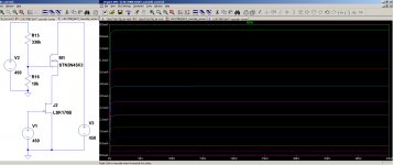
Thanks tikiroo, indeed on the schematic I posted the two resistors between the sources of the jfets and the CCS are actually a trimmer. I set it in order to have the same voltage on both plates of the 12ax7.Can be fixed with a balance pot instead of fixed source resistors.
The reason why I simulated two resistors instead of a trimmer, is that on LTSpice there's need to load the model of the trimmer to use it. And being both sides te same, I just used two resistors of the same value.
Yes, I will do it for sure!Let me know when it all comes out right.
Thanks!
I’ve done some mods and tests yesterday.
Not the full mod I’ve written here because of time.
Best results with cathode feedback through OPT secondary, 43% UL, shunt feedback from EL34’s plates to 12AT7’s grids through 1 MOhm resistors.
Good, better than before, more defined on midrange and with a deeper bass, but I’m sure it can improved further. I will do some scopeing when possible.
I've tested it also without cathode feedback and I like it.
There's no gnfb, and the Raa is 7 kOhm despite the original 3.5 kOhm by connecting the 8 Ohm speakers on the 4 Ohm tap. Based on the 28 H of primary inductance, and actual internal resistance of the pentode, I should have the -3dB point at around 14 Hz and the -1 dB point at 28 Hz. Cannot be noticed any bass roll-off.
There's no gnfb, and the Raa is 7 kOhm despite the original 3.5 kOhm by connecting the 8 Ohm speakers on the 4 Ohm tap. Based on the 28 H of primary inductance, and actual internal resistance of the pentode, I should have the -3dB point at around 14 Hz and the -1 dB point at 28 Hz. Cannot be noticed any bass roll-off.
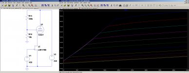
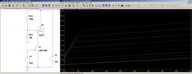
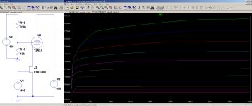
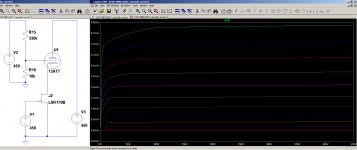
I add here the curves for the PI with 12AX7 (as it is standard) and with 12AT7:
- Changing the voltage divider by increasing the ratio, moves the knees towards the right side of the plot;
- Changing the tube from 12AT7 to 12AX7, moves the knees towards the right side of the plot.
Attachments
Following the suggestion given by kokoriantz here: Question re Allen Wright PP-1cs
I tried this current differential feedback on this circuit. Well, by now I've just simulated it, but results are promising and I will try it in my amp.
The circuit is attached, with Hammond 1650N ( https://www.hammfg.com/files/parts/pdf/1650N.pdf ) it gives 60 Wrms as follows:
And this result at 10 Wrms:
This is the same amp with Toroidy 6600 Raa ( TTG-EL34PP - Tube output transformer [6,6kOhm] 2xEL34 / 2x6L6 Push-pull or similar - Shop Toroidy.pl ) at 45 Wrms:
and at 10 Wrms:
Am I right in saying that the 2nd harmonic should be cancelled but it's not because I do something wrong in the FFT command? Shound it be done on V(Output)-V(n023) but I don't know how to do it.
I tried this current differential feedback on this circuit. Well, by now I've just simulated it, but results are promising and I will try it in my amp.
The circuit is attached, with Hammond 1650N ( https://www.hammfg.com/files/parts/pdf/1650N.pdf ) it gives 60 Wrms as follows:
Code:
Harmonic	Frequency	 Fourier 	Normalized	 Phase  	Normalized
 Number 	  [Hz]   	Component	 Component	[degree]	Phase [deg]
    1   	1.000e+03	2.172e+01	1.000e+00	    0.04°	    0.00°
    2   	2.000e+03	7.942e-02	3.656e-03	   92.55°	   92.51°
    3   	3.000e+03	1.167e-01	5.373e-03	   -4.77°	   -4.81°
    4   	4.000e+03	3.550e-02	1.634e-03	   90.36°	   90.32°
    5   	5.000e+03	1.541e-01	7.093e-03	  179.92°	  179.88°
    6   	6.000e+03	1.480e-03	6.811e-05	   99.38°	   99.34°
    7   	7.000e+03	3.684e-02	1.696e-03	   -1.91°	   -1.95°
    8   	8.000e+03	7.272e-03	3.347e-04	   92.09°	   92.06°
    9   	9.000e+03	1.905e-02	8.771e-04	 -176.24°	 -176.27°
Total Harmonic Distortion: 0.994852%(0.997514%)
And this result at 10 Wrms:
Code:
Harmonic	Frequency	 Fourier 	Normalized	 Phase  	Normalized
 Number 	  [Hz]   	Component	 Component	[degree]	Phase [deg]
    1   	1.000e+03	8.913e+00	1.000e+00	   -0.02°	    0.00°
    2   	2.000e+03	3.986e-02	4.472e-03	   89.98°	   90.00°
    3   	3.000e+03	1.953e-02	2.191e-03	   -0.82°	   -0.80°
    4   	4.000e+03	2.873e-04	3.224e-05	   92.55°	   92.57°
    5   	5.000e+03	3.716e-04	4.169e-05	    0.25°	    0.27°
    6   	6.000e+03	8.920e-05	1.001e-05	  -89.65°	  -89.62°
    7   	7.000e+03	3.035e-05	3.405e-06	  173.19°	  173.21°
    8   	8.000e+03	1.056e-05	1.185e-06	   80.09°	   80.11°
    9   	9.000e+03	4.478e-06	5.024e-07	   17.94°	   17.96°
Total Harmonic Distortion: 0.498014%(0.498013%)
This is the same amp with Toroidy 6600 Raa ( TTG-EL34PP - Tube output transformer [6,6kOhm] 2xEL34 / 2x6L6 Push-pull or similar - Shop Toroidy.pl ) at 45 Wrms:
Code:
Harmonic	Frequency	 Fourier 	Normalized	 Phase  	Normalized
 Number 	  [Hz]   	Component	 Component	[degree]	Phase [deg]
    1   	1.000e+03	1.896e+01	1.000e+00	   -0.01°	    0.00°
    2   	2.000e+03	9.076e-02	4.787e-03	   89.99°	   90.00°
    3   	3.000e+03	2.619e-01	1.381e-02	   -0.29°	   -0.28°
    4   	4.000e+03	2.426e-02	1.279e-03	   89.72°	   89.73°
    5   	5.000e+03	1.411e-02	7.440e-04	 -177.89°	 -177.88°
    6   	6.000e+03	1.297e-03	6.843e-05	  -89.15°	  -89.14°
    7   	7.000e+03	8.626e-03	4.550e-04	    0.77°	    0.77°
    8   	8.000e+03	1.174e-03	6.190e-05	  -94.38°	  -94.37°
    9   	9.000e+03	2.568e-03	1.354e-04	 -179.45°	 -179.44°
Total Harmonic Distortion: 1.470111%(1.470118%)
and at 10 Wrms:
Code:
Harmonic	Frequency	 Fourier 	Normalized	 Phase  	Normalized
 Number 	  [Hz]   	Component	 Component	[degree]	Phase [deg]
    1   	1.000e+03	8.882e+00	1.000e+00	   -0.01°	    0.00°
    2   	2.000e+03	3.233e-02	3.640e-03	   89.95°	   89.96°
    3   	3.000e+03	2.318e-02	2.609e-03	   -0.54°	   -0.53°
    4   	4.000e+03	2.375e-04	2.674e-05	   91.98°	   91.99°
    5   	5.000e+03	4.800e-06	5.404e-07	  172.81°	  172.82°
    6   	6.000e+03	2.415e-05	2.719e-06	  -87.87°	  -87.86°
    7   	7.000e+03	1.889e-06	2.127e-07	  119.01°	  119.02°
    8   	8.000e+03	2.448e-06	2.757e-07	   59.87°	   59.88°
    9   	9.000e+03	1.423e-06	1.602e-07	   34.14°	   34.15°
Total Harmonic Distortion: 0.447888%(0.447888%)
Am I right in saying that the 2nd harmonic should be cancelled but it's not because I do something wrong in the FFT command? Shound it be done on V(Output)-V(n023) but I don't know how to do it.
Attachments
Try altering the minimum step size to say 1us. LT spice is not that accurate in predicting THD.
Thank you Baudoino.
I think it is also related to the fact the the secondary is center grounded, and it is only analysing half of it. Can it be the reason?
I will try your suggestion! Just wondering if it's better a 4k3 (Hammond) or 6k6 (Toroidy) Raa for this configuration.
I think it is also related to the fact the the secondary is center grounded, and it is only analysing half of it. Can it be the reason?
I will try your suggestion! Just wondering if it's better a 4k3 (Hammond) or 6k6 (Toroidy) Raa for this configuration.
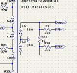
In the command .four freq V(out) choose instead I(R39).
To get accurate distortion measurement, not FFT, choose .tran 11/freq 10/freq 10000/freq to sample 10000 points on single cycle.
To get accurate distortion measurement, not FFT, choose .tran 11/freq 10/freq 10000/freq to sample 10000 points on single cycle.
Last edited:
Tank you kokoriantz, I will try and report he results.
Do you agree wih me that there should be almost no even order distortion being a PP?
Do you agree wih me that there should be almost no even order distortion being a PP?
This is the result for I(R39), so apparently there's mainly 3rd harmonic (good), then a bit of 2nd and 4th that I wouldn't expect, then 5th and others are more than one order of magnitude below 3rd.
It seems good to me. This is 43 Wrms with 550 mVp = 780 mVrms at its input.
Using Hammond 1650N and its 4.3 kOhm Raa I could reach 60 Wrms, but based on simulations I'd get more high order harmonics compared to 6.6 kOhm of Toroidy's OPT.
Code:
Harmonic	Frequency	 Fourier 	Normalized	 Phase  	Normalized
 Number 	  [Hz]   	Component	 Component	[degree]	Phase [deg]
    1   	1.000e+03	2.325e+00	1.000e+00	   -0.07°	    0.00°
    2   	2.000e+03	1.314e-02	5.652e-03	   90.12°	   90.19°
    3   	3.000e+03	3.006e-02	1.293e-02	   -0.44°	   -0.37°
    4   	4.000e+03	3.228e-03	1.388e-03	   90.27°	   90.34°
    5   	5.000e+03	1.183e-03	5.088e-04	 -178.66°	 -178.59°
    6   	6.000e+03	9.132e-05	3.927e-05	  -91.86°	  -91.79°
    7   	7.000e+03	9.022e-04	3.880e-04	    0.83°	    0.90°
    8   	8.000e+03	1.942e-04	8.353e-05	  -90.27°	  -90.20°
    9   	9.000e+03	2.270e-04	9.762e-05	 -179.48°	 -179.41°
Total Harmonic Distortion: 1.419102%(1.419111%)
It seems good to me. This is 43 Wrms with 550 mVp = 780 mVrms at its input.
Using Hammond 1650N and its 4.3 kOhm Raa I could reach 60 Wrms, but based on simulations I'd get more high order harmonics compared to 6.6 kOhm of Toroidy's OPT.
Instead of grounding the 4 ohm of the OPT, let the secondary float with 500 ohms adjust with wiper grounded. By adjusting the wiper you can cancel the even order harmonics. To have perfect adjust, push it to above clipping and adjust for symmetric saturation. In real world with so many components variations, the 500 ohms adjust can bring perfect ac gain balance adjust.
Attachments
Last edited:
Thanks kokoriantz, I tried to do it with the 100 Ohm balance I have on the bottom of the PI, and this is what I get at 43 Wrms:
It seems to me a good harmonic content, and I like the idea to be able to adjust the amount of 2nd order harmonic with the trimmer, as a sonic shaper of the amp.
What is your opinion?
I will try the 500 Ohm pot too, because this will help to avoid buying a custom OPT, so reducing its costs.
Code:
Harmonic	Frequency	 Fourier 	Normalized	 Phase  	Normalized
 Number 	  [Hz]   	Component	 Component	[degree]	Phase [deg]
    1   	1.000e+03	1.859e+01	1.000e+00	   -0.07°	    0.00°
    2   	2.000e+03	9.447e-04	5.083e-05	  122.19°	  122.26°
    3   	3.000e+03	2.422e-01	1.303e-02	   -0.44°	   -0.36°
    4   	4.000e+03	2.828e-02	1.521e-03	   90.12°	   90.19°
    5   	5.000e+03	9.217e-03	4.958e-04	 -178.67°	 -178.59°
    6   	6.000e+03	4.079e-04	2.195e-05	   95.19°	   95.26°
    7   	7.000e+03	7.126e-03	3.834e-04	    0.82°	    0.90°
    8   	8.000e+03	2.159e-03	1.161e-04	  -89.58°	  -89.51°
    9   	9.000e+03	1.738e-03	9.348e-05	 -179.50°	 -179.43°
Total Harmonic Distortion: 1.313527%(1.313534%)
It seems to me a good harmonic content, and I like the idea to be able to adjust the amount of 2nd order harmonic with the trimmer, as a sonic shaper of the amp.
What is your opinion?
I will try the 500 Ohm pot too, because this will help to avoid buying a custom OPT, so reducing its costs.
- Home
- Amplifiers
- Tubes / Valves
- improvements on 12AX7 12AT7 EL34 schematic?