Hello AngelP,
Unfortunately, this is not entirely true.
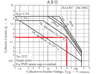
Permissible DC current at 50 V
TTK004/2SC3902
Unfortunately, this is not entirely true.
Permissible DC current at 50 V
TTK004/2SC3902
Attachments
Last edited by a moderator:
Hello all,
I recently have had an interesting issue which I would like to share, actually revisiting what was discussed in post #320 on pg. 16.
(Yes, this thread is getting very long).
It is about the capacitor that (sometimes) is placed around the bias transistor circuit. Values I have seen in amp designs range from 10nF to 47uF.
And still to date I haven't found any textbook or serious article description of the 'raison d'etre' for this capacitor - or how to properly design its value.

Recently I had a beautiful, original RA-810A on the bench to upgrade. After opening the box, I first noted that the left channel had this C613 bypass cap - but the right channel had nothing???
So I decided to put in a 1uF film cap as I usually do (although this time before starting the actual upgrade). And soon the circuit went hot.
Scope on - and oops, there was severe HF oscillation. Removed the 1uF - and the oscillation was gone. Hmm.
Apparently these bias bypass caps are maybe not as innocent as they seem? 🤔
Anyway, I then completed the full upgrade successfully and thought little more about it as the amp was rock stable - and sounded fabulously.😍
But the next 'customer' on the bench was a heavy non-working RB-980BX. The four T4A secondary fuses had been replaced with T7.5A (!) and the bridge rectifiers had blown. Something was seriously wrong with this amp.
While I was waiting for delivery of the new rectifiers, I removed the 7.5A fuses and powered one channel up using lab supplies with current limits set at 250mA.
At first the supply currents looked relatively ok, but when I briefly touched the 10uF bypass cap the limiters immediately set in.
Scope on - and there was a large 1MHz oscillation.
Trusted remedy - two 100pF Miller caps from the base to collector of the VAS trannies immediately stopped it, currents normal - problem solved.🙂👍
But being an upgrader rather than an repairer, my curiosity had already been triggered and I just had to investigate and experiment a bit.
So I first tried reducing the Millers to 15pF - and the oscillation returned. Then up to 47pF where things went stable.
Eventually remembering the RA-810A - what if I instead just removed all Millers and the 10uF bias bypass cap? So I did - and the amp was stable.
The VASs, the bias tranny and the 10uF cap were then all measured out of the circuit and were fine. All drivers and power trannies were also ok, and so were the current sources for the LTP's. No other visible or obvious damages that may have caused the problem.
I guess that left the LTPs. They actually measured ok (although there was not much hFE matching left) and the thermal compound in the plastic tubes had turned brown from heat. Even so, they worked just fine - once the 10uF bias cap was gone.

If anyone on this thread has had any similar experiences - or even better, a plausible explanation to the above, I am definitely all ears....
And also 'all eyes' if someone has a link to a relevant paper on the issue.
Per
I recently have had an interesting issue which I would like to share, actually revisiting what was discussed in post #320 on pg. 16.
(Yes, this thread is getting very long).
It is about the capacitor that (sometimes) is placed around the bias transistor circuit. Values I have seen in amp designs range from 10nF to 47uF.
And still to date I haven't found any textbook or serious article description of the 'raison d'etre' for this capacitor - or how to properly design its value.
Recently I had a beautiful, original RA-810A on the bench to upgrade. After opening the box, I first noted that the left channel had this C613 bypass cap - but the right channel had nothing???
So I decided to put in a 1uF film cap as I usually do (although this time before starting the actual upgrade). And soon the circuit went hot.
Scope on - and oops, there was severe HF oscillation. Removed the 1uF - and the oscillation was gone. Hmm.
Apparently these bias bypass caps are maybe not as innocent as they seem? 🤔
Anyway, I then completed the full upgrade successfully and thought little more about it as the amp was rock stable - and sounded fabulously.😍
But the next 'customer' on the bench was a heavy non-working RB-980BX. The four T4A secondary fuses had been replaced with T7.5A (!) and the bridge rectifiers had blown. Something was seriously wrong with this amp.
While I was waiting for delivery of the new rectifiers, I removed the 7.5A fuses and powered one channel up using lab supplies with current limits set at 250mA.
At first the supply currents looked relatively ok, but when I briefly touched the 10uF bypass cap the limiters immediately set in.
Scope on - and there was a large 1MHz oscillation.
Trusted remedy - two 100pF Miller caps from the base to collector of the VAS trannies immediately stopped it, currents normal - problem solved.🙂👍
But being an upgrader rather than an repairer, my curiosity had already been triggered and I just had to investigate and experiment a bit.
So I first tried reducing the Millers to 15pF - and the oscillation returned. Then up to 47pF where things went stable.
Eventually remembering the RA-810A - what if I instead just removed all Millers and the 10uF bias bypass cap? So I did - and the amp was stable.
The VASs, the bias tranny and the 10uF cap were then all measured out of the circuit and were fine. All drivers and power trannies were also ok, and so were the current sources for the LTP's. No other visible or obvious damages that may have caused the problem.
I guess that left the LTPs. They actually measured ok (although there was not much hFE matching left) and the thermal compound in the plastic tubes had turned brown from heat. Even so, they worked just fine - once the 10uF bias cap was gone.
If anyone on this thread has had any similar experiences - or even better, a plausible explanation to the above, I am definitely all ears....
And also 'all eyes' if someone has a link to a relevant paper on the issue.
Per
The four T4A secondary fuses had been replaced with T7.5A (!) and the bridge rectifiers had blown.
Hello AngelP,
I recommend to install high-speed ceramic series F for example Siba.
It is about the capacitor that (sometimes) is placed around the bias transistor circuit. Values I have seen in amp designs range from 10nF to 47uF.
And still to date I haven't found any textbook or serious article description of the 'raison d'etre' for this capacitor - or how to properly design its value.
Its purpose is to shunt the alternating current, although low, but the collector-emitter resistance of the bias transistor.
Attachments
Hi Sam,
Yes, I know that this bias stage bypass capacitor does speed up the turn-off action of the drivers. Doug Self notes that "its use has been questioned because of the possibility of unhelpful charges building up on it during asymmetrical clipping". So, the issue must have been extensively discussed somewhere, but he gives no link to any reference.
How should its value be determined - Empirically? By trial and error? And why/how can it cause oscillations?
Bob Cordell suggests to instead put in an emitter follower after the bias stage which would dramatically reduce its output impedance - across the entire frequency spectrum.👍 But that is not straightforward in an upgrade of an existing amp layout.
I thought of testing whether the 1MHz oscillation was due to parasitic capacitances in the power stage by soldering the 10uF Black Gate back in again and put in a 15pF between one of its legs to ground. Alas, the old black cap had already been sent to recycling, so it is probably in a landfill somewhere. 🙄
I may have another used 10u Black Gate lying around which I could try and see if the oscillation returns - and if so, whether a small cap to ground helps.
Anyway, I guess that the rule of thumb is that if you have an amp that has suffered serious and damaging oscillations - you should assume that all electrolytic capacitors have been damaged by heavy reverse polarity voltages. And simply replace them all.
An emitter follower can draw unexpectedly large currents from its input (base) if the output (emitter) voltage goes wacky. I avoid placing capacitors on the inputs of emitter followers to give the circuit one fewer thing that can go wrong.
The Vbe multiplier already has low impedance.
Ed
The Vbe multiplier already has low impedance.
Ed
I thought of testing whether the 1MHz oscillation was due to parasitic capacitances in the power stage by soldering the 10uF Black Gate
Hello AngelP,
The amplifier is not stable, either a malfunction or modifications have made it so.
Hi all,
I normally let people have their opinions, but I think I should counter Sam's last post above on C607 as I don't believe it to be correct.
I have by now done a lot of web searching and textbook reading on this bias cap issue. And it appears that..... the jury is still out.
There does not seem to be any firm consensus on function nor indeed any design recommendations. What I maybe can conclude and share is:
This capacitor that (sometimes) is placed to bypass the bias transistor (aka. Vbe multiplier) circuit has one main function - to ensure that there is enough current capacity to suck carrier charge out of the following drivers and thus enable a fast cut off to avoid them being 'on' at the same time, causing distortion.
As I wrote in an earlier post, I have seen values in commercial amps ranging from 0.1 to 47uF (try to get that as an NPO).😉
It has no HF stabilising function in the amp per se. But it does add to the load on the VAS collector(s).
In conclusion, my claim is:
If you have a proper and stable amp design - you can put almost any value in.
If not - any value (even zero) will sustain or add to the chance of instability.
(ok, just call me Sherlock).🔎
However, I can back that up with a range of experiments I recently did on the RB-980BX that was oscillating badly.
The amp could easily be made stable by adding two 47pF Miller caps from the VASs' c to b - with or without the 10uF bypass cap (or any other value).
Then, at first it strangely seemed to become stable even without the Millers when the 10uF bypass cap was removed.
Alas, a bit later when the quiescent current was slowly increased towards the set value it started to oscillate again - although at a different frequency.
So, I had before me an original amp that had somehow become unstable, and I decided to find out why and which component(s) were responsible.
I started by replacing all electrolytic caps, measure all resistors and film caps and re-solder all joints. Still unstable.
Then I meticulously replaced the semiconductor stages one by one from the LTP to the output stage and checked in between. Still unstable.
I now had an original commercial amp design with all brand new and unstressed components - which was unstable even under safe lab bench current supply control. (Correction, it appeared stable until any significant output quiescent current was started.)
Could this mean that the Rotel RB-980BX design is marginally unstable? I find that hard to believe, in particular because of the many Rotels I have had on my workbench which never gave such indication. Any suggestions of what issues I could have missed?🤔
Anyway, for the RB-980BX it is now already too late.
I have upgraded the entire amp with CM2 and VAS12 modules and a new CS1 current source module for the VAS current in place of the 330p C611/612. The amp is absolutely rock stable and sounds superbly better. THD down by 20dB, slew rate doubled, temperatures well controlled, etc......
I could even remove the two 220p pre-driver collector to base capacitors without any stability issues. The 56pF PS Millers did the job.
As for the wretched C609/610 bias bypass caps........ well, I simply decided to put in 1uF WIMA film capacitors as I usually do.😊
Per
Last edited:
As I wrote in an earlier post, I have seen values in commercial amps ranging from 0.1 to 47uF (try to get that as an NPO).😉
In post #889, I talked about C607 NPO 330 pF from the section of the circuit given there, and not about C613. In post #890 it's C611.
Last edited:
Hi Sam,
I am sorry that you are confused. I (and probably others) didn't notice that you changed the subject from the circled component, so let me try to clarify:

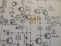
I was talking about the capacitor marked in yellow, whereas I think that you are about the ones in blue. Ok, let's discuss the blue ones in this post.
These are Rotel's unique way of stabilising the amp, providing a heavy lag load on the VAS collector. Most often they put in a parallel 33k resistor as in the RA-810A schematic above. It is brutal way of quenching oscillations, but it works (albeit with the resulting audible Rotel "softness" distortion).
Note the complete absence of b-c Miller capacitors around the VASs Q607/608.
Is the value critical? Well, yes and no.
Note the 30% (!) variability in value in the note box on the left bottom depending on what I always believed to be 'region' - but I am not absolutely sure what "RUK" stands for. (I mean, it can't be "Republic of the United Kingdom" as that would be quite an oxymoron.)😊
Does anyone reading this thread know?
And what regional(?) differences would warrant such differences?? Anyone?
Yes, if you use ceramic caps here they should always be NPO, although after the 800 series Rotel switched to Polystyrene film caps.
The caps marked in yellow is another issue. Why should one 10nF be used in the right channel, but (sometimes) not in the left?
And as they don't directly contribute to amp circuit stabilisation - why would placing a cap there cause instability? That is the subject of the next post.
Stay tuned.
I am sorry that you are confused. I (and probably others) didn't notice that you changed the subject from the circled component, so let me try to clarify:
I was talking about the capacitor marked in yellow, whereas I think that you are about the ones in blue. Ok, let's discuss the blue ones in this post.
These are Rotel's unique way of stabilising the amp, providing a heavy lag load on the VAS collector. Most often they put in a parallel 33k resistor as in the RA-810A schematic above. It is brutal way of quenching oscillations, but it works (albeit with the resulting audible Rotel "softness" distortion).
Note the complete absence of b-c Miller capacitors around the VASs Q607/608.
Is the value critical? Well, yes and no.
Note the 30% (!) variability in value in the note box on the left bottom depending on what I always believed to be 'region' - but I am not absolutely sure what "RUK" stands for. (I mean, it can't be "Republic of the United Kingdom" as that would be quite an oxymoron.)😊
Does anyone reading this thread know?
And what regional(?) differences would warrant such differences?? Anyone?
Yes, if you use ceramic caps here they should always be NPO, although after the 800 series Rotel switched to Polystyrene film caps.
The caps marked in yellow is another issue. Why should one 10nF be used in the right channel, but (sometimes) not in the left?
And as they don't directly contribute to amp circuit stabilisation - why would placing a cap there cause instability? That is the subject of the next post.
Stay tuned.
Last edited:
These are Rotel's unique way of stabilising the amp,
This is exactly what I pointed out in terms of instability.
Ok, then please do share your superior knowledge on this issue with us mortals:
1) How does it achieve the stabilisation?
2) How is its value determined?
3) What are the acceptable tolerances of this value?
4) What is the effect of the parallel resistor?
5) Why are there regional differences in value?
6) What happens if you put in, say, a 1nF (or 10nF) instead?
7) Does VAS current play any role?
8) Does it cause any distortion, if so, what and by which amount?
9) Links to relevant technical articles on the issue would be welcome (though not in cyriilic, please).
Looking forward to be enlightened.
Don't know what RUK may be, but out of curiosity I checked the service manual for the 976 and noticed something similar:
C607 / 608 (blue capacitors) are tagged 330pF in the schematic, but 270 pF in the BoM
C611 / 612 (in the -976 schematic, C613 / C614 in schematic above) er 1uF polarized in schematic and BoM
C607 / 608 (blue capacitors) are tagged 330pF in the schematic, but 270 pF in the BoM
C611 / 612 (in the -976 schematic, C613 / C614 in schematic above) er 1uF polarized in schematic and BoM
6) What happens if you put in, say, a 1nF (or 10nF) instead?
This will lead to amplifier instability (changing the values of any polystyrene capacitor, regardless of its location on the circuit).
AngelP - See this article. https://en.wikipedia.org/wiki/Bode_plot#Gain_margin_and_phase_margin
The capacitor creates a dominant pole whose purpose is to reduce the gain around the loop to much less than unity by the frequency at which the phase reaches -180 degrees. To size the capacitor, you need to compute the loop gain and the frequency of the second pole. This requires small-signal analysis or Spice simulation (most DIY'ers opt for the latter).
Ed
This will lead to amplifier instability (changing the values of any polystyrene capacitor, regardless of its location on the circuit).
Oh, really?
Funny that, I just tried it out on one of the (too) many Rotels standing on the floor in my workshop.
I put in a 1nF and it did not change any polystyrene capacitor's value. 🤣 Ok, sorry - serious hat on🎩:
The amp sounds like a cheap transistor radio - but it is definitely stable. So, I tried a 1uF - still stable.
Then, for fun and giggles, I tried changing the other PS caps from 50% to 150% of their original value - still stable.
QED - Your statement is false.
I normally tolerate or even welcome lack of knowledge on this thread - as we are all here to learn.
But you seem to climb the high horse of pretend authority - yet do not manage to spread anything other than what comes out of said animal's rear.
You first answered only one of my nine questions - wrongly. The second two-word answer sounds more like what you perhaps should be in.
I am sorry, that does not quite amount to a pass for a diploma in audio engineering.😢
Maybe better luck on another thread?
LJT - Rotel soon settled on 330pF PS, did you check what is actually on the pcb?
EdGr - exactly.
The trouble is that stray capacitances from the pcb layout enters the fray - which could be a plausible reason for the difference between the R and L channel in the RA-810A. Spice wouldn't be able to know that.
EdGr - exactly.
The trouble is that stray capacitances from the pcb layout enters the fray - which could be a plausible reason for the difference between the R and L channel in the RA-810A. Spice wouldn't be able to know that.
- Home
- Amplifiers
- Solid State
- Improve a Rotel amp THD by 20dB!