Back on to the oscillating RB-980BX - which is quite another kettle of beast compared to the small RA-810A.
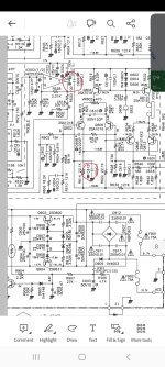
This pic shows the components responsible for the amp's stability, circled in... well, some lipstick colour.

It is actually a stretch to circle in the first RF quencher cap C603 and the Zobel network at the far right of the pic, as these only kick in when certain external factors appear. And note that the bias capacitor C609 is not circled.
C605 limits HF gain, this has been discussed earlier on this thread, but I just can't find the posts now, sorry - it has indeed become a very long thread.
But if you are interested, there is a good TI article on it, https://www.ti.com/lit/an/slyt630/slyt630.pdf?ts=1686932296947
This leaves three capacitors, C611, 613 and 615.
C611 and C615 are effectively in parallel through the reservoir cap, so the VAS collector load is 550p - plus component and stray capacitances.
With the 10uF bias cap C609 in place, it partly shorts in C613 to come into play as seen from the VAS, making the load over 770pF.
Maybe good for stability, but perhaps not so good for slew rate and distortion.
So I started the APS upgrade. Here is first what I removed for replacing - or for good.

Looks a bit threadbare, right? You should see the pcb...... but hey, cleaning it is now easy!
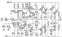
I use my SMD modules throughout and drawing in the complete circuit would make it very hard to view.
So here is the resulting simplified schematic. Each of the modules have been described previously, CM2 are improved Wilson Current Mirrors, VAS12 are EF-CM-dualVAS (both in NPN and PNP versions) and CS1 is the new 3mA current source module for VAS current control.

The original three stability caps are gone, replaced with 56p Miller caps in the VAS12 modules. New LTP pairs have emitter degrading caps and their DC current has been increased. Slew rate is doubled and distortion is >0.0028%.
Component temperature is well controlled to be below 50degC overall and the sound is absolutely outstanding.
This RB-980BX has been totally transformed - and in case you were wondering..... yes, it is rock stable.😍
I now await the response from the amp's owner and maybe post it here.
Per
This pic shows the components responsible for the amp's stability, circled in... well, some lipstick colour.
It is actually a stretch to circle in the first RF quencher cap C603 and the Zobel network at the far right of the pic, as these only kick in when certain external factors appear. And note that the bias capacitor C609 is not circled.
C605 limits HF gain, this has been discussed earlier on this thread, but I just can't find the posts now, sorry - it has indeed become a very long thread.
But if you are interested, there is a good TI article on it, https://www.ti.com/lit/an/slyt630/slyt630.pdf?ts=1686932296947
This leaves three capacitors, C611, 613 and 615.
C611 and C615 are effectively in parallel through the reservoir cap, so the VAS collector load is 550p - plus component and stray capacitances.
With the 10uF bias cap C609 in place, it partly shorts in C613 to come into play as seen from the VAS, making the load over 770pF.
Maybe good for stability, but perhaps not so good for slew rate and distortion.
So I started the APS upgrade. Here is first what I removed for replacing - or for good.
Looks a bit threadbare, right? You should see the pcb...... but hey, cleaning it is now easy!
I use my SMD modules throughout and drawing in the complete circuit would make it very hard to view.
So here is the resulting simplified schematic. Each of the modules have been described previously, CM2 are improved Wilson Current Mirrors, VAS12 are EF-CM-dualVAS (both in NPN and PNP versions) and CS1 is the new 3mA current source module for VAS current control.
The original three stability caps are gone, replaced with 56p Miller caps in the VAS12 modules. New LTP pairs have emitter degrading caps and their DC current has been increased. Slew rate is doubled and distortion is >0.0028%.
Component temperature is well controlled to be below 50degC overall and the sound is absolutely outstanding.
This RB-980BX has been totally transformed - and in case you were wondering..... yes, it is rock stable.😍
I now await the response from the amp's owner and maybe post it here.
Per
I normally tolerate or even welcome lack of knowledge on this thread - as we are all here to learn.
Usually I do too, but since post 881 I no longer want to answer.
Study theory because you have little knowledge
Last edited:
Hi PakaPL,
Firstly, the RA-840BX4 is one of Rotels circuit designs which I am perhaps less familiar with. I have repaired a few, but never upgraded one with current mirrors and VAS's.
But there are definitely a few things you could do. 400mV ripple on +/-B1 is too much.
In comparison, an RA-931 has about 30-40mV ripple on its rails and a few mV after the filters.
If you haven't already done so, you could consider changing the reservoir capacitors C909/910 to modern 63V 10,000uF low ESR types that physically fits into place. And the B3 rail's C923 to a low ESR 63V rated with as much capacity as will fit onto the pcb.
Secondly, these days I don't bother with the input cascode design, the input stage filter does the job.
The easy way for you is to replace C619-622. The C619/620 with 100uF Panasonic FM's and the C621/622 with 0.47 or 1uF caps. My TM copy does not show the pcb tracks well, so you may have to find out where to drill some new 0.8mm holes in the right places to fit the caps in.
The 100 ohm resistors go in the B3 rails between the C923 and input stage rails, again, I can't clearly see where, but you will have to cut the track(s) and bridge with the 100 ohms. The negative rail already has a 120k which with a good quality 1 uF should give plenty of ripple reduction.
Remember to put in the electrolytics the right way round, or else there will be smoke.
Thirdly, am I right that the power resistors R641-644 get very hot? The ones in e.g. the RA-940/960BX definitely do (126 degC), see enclosed pics. And they fry the pcb and all surrounding componets. So, in the RA-980BX Rotel removed them and reverted to the more straightforward 47 Ohms 0.5W between the two Q623/625 driver emitters. Works as a treat and stops global warming.
Remember to cover the 47 R’s in a insulating sleeve to avoid accidental shorts if mounted on the pcb track side.
Happy modding!
Cheers,
Per
Hi,
Old Post to quote I know but are these mods applicable to the RA940 as well?
Thanks
Hi Chris,
Yes, although the components of course have different pcb numbers from the RA-840BX. And there is no 'B3' rail in the 940.
The main thing that I would change is the R663 to R666 power resistors, as I guess that they show signs of having been way too hot?
Remove them and put a 47 ohm 0.5W resistor in between the emitters of Q623 and Q625 (and between Q624 and Q626).
You can use the 'outer' pcb holes where the power resistors sat.
Best,
Per
Thanks Per,
The schematics are different between mobiles obviously, see if I have this correct? The capacitors seem to be in the same place (please see attached pic) what difference does this make? The 100ohm resistor doesn't go anywhere as there's no B3.
The schematics are different between mobiles obviously, see if I have this correct? The capacitors seem to be in the same place (please see attached pic) what difference does this make? The 100ohm resistor doesn't go anywhere as there's no B3.
Sorry, bit unclear that
So on the 940bx schematic I take it that c606 and c612 and the same on the other channel are the equivelent to c619-622 on the 840bx (see attached pic) what does replacing these do?
Are there any other worthwhile mods to do to the 940bx
So on the 940bx schematic I take it that c606 and c612 and the same on the other channel are the equivelent to c619-622 on the 840bx (see attached pic) what does replacing these do?
Are there any other worthwhile mods to do to the 940bx
Attachments
Basically, C611/12 forms a 13Hz low pass filter with R629/30 to filter out any 100Hz hum from the -18.6V rail of the LTP (Q601/02 and Q605/06).
I am not entirely sure why C605/06 was put in going from V+ to this -18.6V point. (And it is not a drawing mistake in the schematic).
But as it sits in series with the massive reservoir capacitor C909, it is essentially in parallel with C611 and thus should halve the 13Hz low pass frequency.
It will also inject hum and noise from the V+ rail to the -18.6V point, but that noise is in (broadly) the same phase as the V+ noise, possibly countering the effect of it on the LTP stage?
I would have to do more analysis and actual measuring to confirm this, but I don't have a RA-940BX at hand. So until then, I suggest to leave it as it is.
My original suggestion some years back was based on my fiddling with extra R-C rail filters to reduce hum ripple to the input stages. I have since found that if you use perfectly matched transistor pairs, the PSRR shoots up and the bother of applying such extra filtering components can be avoided.
What I would do today to upgrade a RA-940 would probably be to put in such matched LTPs. Then perhaps improve the preamp stage by replacing the old NE5532s with OPA2134 or OPA1612 (Sacrilege!!! I hear some shout 😱).
But these OPAs have also decent DC offset properties, so it is possible to DC couple the preamp to the power stage by shorting the electrolytic caps C505/515 and 517. And in the 940 there is even an offset adjustment pot to null out any remainder.
Do note that if your tone switch has starting to have oxidised internal contact rail points, you may get a thump when turning the tone knob.
And unsoldering, disassembling, cleaning and reassembling these old rare ALPS switches is not for the faint hearted!
I may eventually do a post on that.
Keep C501/502 in, but replace with film caps if you can find some that fits in. Otherwise use good quality bipolar caps.
The phono stage is well designed and tuned, but maybe upgrade the opamps to OPA134s - if you can get hold of any these days.🙁
And in general, all electrolytic caps are now over 30 years old and should be checked or replaced.
This amp runs quite hot inside, so replace the four 1k (3 or 5W?) driver stage emitter resistors with the two single 0.5W 47 ohm as described above.
Best of luck,
Per

Thanks Per, I shall order some parts and see how it goes.
Just a further question, c503/4 are what look like higher quality poly caps, what are they doing and should they be replaced with better?
Just a further question, c503/4 are what look like higher quality poly caps, what are they doing and should they be replaced with better?
These capacitors are part of the feedback network.
The power stage of this amp is inverting, and can be drawn as an 'ideal' opamp with the NFB network like this:

At DC, the gain is -(121+68) / 15 or -12.6 because the capacitor isolates the 18k from the circuit.
As we begin to move up towards the audio frequency range, the 2u2 starts to conduct and engages the 18k.
At higher frequencies it acts as a short and the gain can be calculated as -35.
It is a clever way of getting high gain without using high value (and thus noisy) resistors.
Just think of it - to get a gain of -35 with the 15k in the input you would need over 500k in the feedback.
It also significantly increases the input impedance, although that is not really important here.
I can't see why they need to be 160V devices, but I remember that there were few choices for affordable high capacity caps back in those days.
It would most often come down to these high voltage metalised polyester as they were widely used in valve based amps, radios and TVs.
You could try to find a modern PP or PC type cap, there is definitely plenty of room for one.
Personally however, I think that the audible difference will be small - but I maybe wrong, so worth a try?
Per
The power stage of this amp is inverting, and can be drawn as an 'ideal' opamp with the NFB network like this:
At DC, the gain is -(121+68) / 15 or -12.6 because the capacitor isolates the 18k from the circuit.
As we begin to move up towards the audio frequency range, the 2u2 starts to conduct and engages the 18k.
At higher frequencies it acts as a short and the gain can be calculated as -35.
It is a clever way of getting high gain without using high value (and thus noisy) resistors.
Just think of it - to get a gain of -35 with the 15k in the input you would need over 500k in the feedback.
It also significantly increases the input impedance, although that is not really important here.
I can't see why they need to be 160V devices, but I remember that there were few choices for affordable high capacity caps back in those days.
It would most often come down to these high voltage metalised polyester as they were widely used in valve based amps, radios and TVs.
You could try to find a modern PP or PC type cap, there is definitely plenty of room for one.
Personally however, I think that the audible difference will be small - but I maybe wrong, so worth a try?
Per
Per,
After reading the more recent posts concerning current mirrors in the LTPs I looked back through some of the earlier posts in this thread and saw the RB-980BX upgrade in Post #397 where a pair of EF transistors were added between the input and the VAS as part of that upgrade.
I then read through Post #422 which included a detailed breakdown of the similar RA-971's input and VAS DC circuit analysis. Using Ohm's law it looks like the RB-980BX's current source should be calculated as (0.65V/383R) = 1.7mA pulled through the LTP, but the RB-980BX schematic in Post #397 shows 2.3mA through the LTP.
Is the difference just due to real world vs. theoretical or is it being affected through other means? Any help in better understanding the circuit would be greatly appreciated. Thank you!
Hi Sam,
Thank you very much for actually reading my rambling, at times it feels a bit like posting into an empty space.
And you have every reason to be confused. occasionally my brain works too fast (some say not at all) for my typing.
In post #442 (pg. 22) there is obviously a typo in the 971 DC analysis, I quote:
So the current through each 1k5 collector resistor is 1.5mA, leaving a voltage across it of 2.25Vdc.
This voltage drop is also present at the VAS transistor base, and subtracting its Vbe gives 1.4Vdc over the 365R resistor. Therefore, the resulting VAS stage current will be (1.4V/365R) = 4.4mA.
2.25V - 0.6V is of course not 1.4V - but 1.65V. Which over a 365R does indeed give the 4.4mA (4.5mA actually).
But apart from that unfortunate typo, the DC analysis in the post is correct, I believe.
In essence, the DC voltage at the LTP collector decides the VAS emitter DC voltage, and the VAS current can (and should only be) adjusted by altering its emitter resistor value. Of course you can only do that if the available LTP collector voltage is more than the VAS' Vbe (2 x Vbe in an EF-VAS).
Post #397 (pg.20)
It has been a few years now, but I think the 383R LTP current source resistors in post #397 was one of my first ways of reducing the VAS current to about 4-5mA (albeit definitely not the optimal way).
With 383R the current sources would only give 1.5mA (not 2.3mA, sorry), thus 0.78mA through each branch of the two LTPs.
0.78mA across the 2k15 collector resistor gives 1.68V, and thus (1.68 - 2x0.6) = 0.48V over the original 100R VAS emitter resistor. Result: 4.8mA VAS current.
I think that I just used an old scribbled draft schematic page to indicate the changes, so just ignore the greyed out current annotations.
I hope this explains things, if not please do not hesitate to ask for further.
Per
Thank you Per! That all makes perfect sense now - and I'm glad that I'm not going crazy (well, at least not yet!)
One other related topic to pose a question on: Theoretically, even without upgrading to current mirrors for the input stage, is there any value in using any emitter degrading resistors with the original current source circuit? Possibly upping the current source to around 4mA and adding 47R or 68R degrading resistors on the LTP emitters? I believe that there was a schematic posted a little while ago of a RB-980BX with possibly some thoughts along these lines?
One other related topic to pose a question on: Theoretically, even without upgrading to current mirrors for the input stage, is there any value in using any emitter degrading resistors with the original current source circuit? Possibly upping the current source to around 4mA and adding 47R or 68R degrading resistors on the LTP emitters? I believe that there was a schematic posted a little while ago of a RB-980BX with possibly some thoughts along these lines?
Hi Sam,
Adding emitter degeneration resistors is definitely a good idea - with or without current mirrors (which BTW is also a very good idea, but perhaps more fiddly).
I can't remember if I have already explained the virtues of emitter degradation on this thread, but in short:
Every BJT exhibit a finite collector to emitter 'resistance' when operating in the active area. Rule of thumb is 'Re' = 25 / Ic (in mA).
So if you f.ex. send 1mA down each LTP transistor, they will have 25 ohms in internal 'resistance'.
Unfortunately, this 'Re' is non-linear and thus contributes to input stage distortion. Double the collector current will of course halve this, and if you then add the now 'missing' 12.5 ohm with an external linear R's you end up with the same c-e 'resistance' - but (more) linear' and less distorting.🙂👍
In practice, higher external values are used to "swamp" the remaining non-linear 'Re'. Self often suggests 100 ohm, Cordell even up to 470 ohm.
I am a bit more careful and use 68 ohm and only increase the current source by 50% to keep the heat shrink wrapped LTPs from heating up too much.
As a bonus, the increased Ic also speeds up the amp's slew rate by draining the Miller caps faster. A clear win-win!😍
Per
Hi Per,
For the RA-971 and its variants, without really knowing what I'm doing, I have tried to distill the content of this thread to a variation of the mod that only changes passive components. What I'm trying to do here is arrive at the furthest extent of modification that is possible without drilling holes or requiring auxiliary boards.
Any thoughts on whether what I have sketched out below makes any sense on its own would be greatly appreciated. Does it even makes sense to think of a passive-only mod as a stepping stone to the more elaborate changes you have come up with?
I'm really greatful for all the work you have put into helping us understand these amps better. Rotels are great to work on, and to know that they can even be significantly improved is quite motivating and inspiring.
Thanks for any insight you might be able to provide to this approach!
Tom
Attachments
Last edited:
Hi Tom,
Thank you for your kind words.
Yes, that would be a good start, and probably reduce THD somewhat. (Although you need to short C601 and change R623 to 365R as well as R621.)
In fact you are making all the right noises - but staying short of the thing that would give you the real "bang for the buck" - the EF transistors.

I may have shown this revised 971 upgrade before, it is what I call the "light" upgrade version, and it does works well.
Admittedly the EF trannies will require two small track cuts and four 0.8mm holes with some green lacquer scraping around them.
But it is all easily reversible in the unlikely event that you'd ever want to go back to stock.
(That said, I'll readily admit that I don't like cutting, drilling and scraping tracks either - which is why I made the SMT modules in the first place.)
Anyway, since you are keeping the original LTPs and DC coupling the power stage, you'll need to check the final output offset - as well as output stability to make sure that you have placed the 47p Miller caps in their right places.
There are actually other DIY'ers that have asked me for more detailed instructions for the 'light' version, so Iet me see what I can do to perhaps suggest the easiest EF tranny placements and connections.
Best,
Per
Thank you for your kind words.
Yes, that would be a good start, and probably reduce THD somewhat. (Although you need to short C601 and change R623 to 365R as well as R621.)
In fact you are making all the right noises - but staying short of the thing that would give you the real "bang for the buck" - the EF transistors.
I may have shown this revised 971 upgrade before, it is what I call the "light" upgrade version, and it does works well.
Admittedly the EF trannies will require two small track cuts and four 0.8mm holes with some green lacquer scraping around them.
But it is all easily reversible in the unlikely event that you'd ever want to go back to stock.
(That said, I'll readily admit that I don't like cutting, drilling and scraping tracks either - which is why I made the SMT modules in the first place.)
Anyway, since you are keeping the original LTPs and DC coupling the power stage, you'll need to check the final output offset - as well as output stability to make sure that you have placed the 47p Miller caps in their right places.
There are actually other DIY'ers that have asked me for more detailed instructions for the 'light' version, so Iet me see what I can do to perhaps suggest the easiest EF tranny placements and connections.
Best,
Per
Thank you Per!
Just to avoid confusion if anyone uses my mark-up, here it is corrected as you noted.
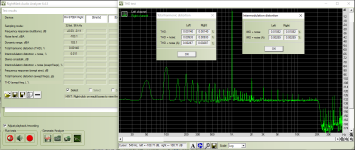
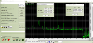
After completing these mods (in addition to a general re-cap and op-amp swap), this is the result I'm measuring (with I think quite reasonable 8mV DC offset).
Where would you scope to check for stability?
Cheers,
Tom
Just to avoid confusion if anyone uses my mark-up, here it is corrected as you noted.
After completing these mods (in addition to a general re-cap and op-amp swap), this is the result I'm measuring (with I think quite reasonable 8mV DC offset).
Where would you scope to check for stability?
Cheers,
Tom
Attachments
Hi Tom,
That is a very impressive distortion that you've achieved! 👍
Some may remember that at the start of this long thread I struggled long and hard to get it below 0.003% without any VAS changes. Ok, that was on an old RA-820BX.
I might just try this on a RA-980BX which I have standing grinning at me on the floor.
I would definitely put a scope on the output - or for those who don't have one, at least a good DMM on AC setting.
An old idea is to try 'teasing' the circuit by introducing some hum by touching transistors and capacitors to see if you can trigger any instability.
I've never seen that work on a Rotel, though.
The 971 does have a 10R / 100n Zobel network to protect against heavy inductive loading, but no output L/R inductor against capacitive loads.
So if you want to be on the very safe side, the standard test is to load the output with 8 ohm || 2 uF - feed the amp with a square wave and watch the scope. Keep a keen eye on both scope and power transistor temperature. Do NOT go for a cuppa with any such test running!
Once you're happy please let us know how it sounds. After all, that is the most important result of all these shenanigans.
Per
Hi again Tom,
I note that you increased the LTP currents, but did not put in emitter degrading resistors. You may want to reconsider that, see why in post #846.
It can be done without cutting tracks or drilling holes.
Per
I note that you increased the LTP currents, but did not put in emitter degrading resistors. You may want to reconsider that, see why in post #846.
It can be done without cutting tracks or drilling holes.
Per
Hi Per,
Indeed! I had coloured those LTP resistors blue rather than red because I had not yet changed those, and I don't think I will.
This amp seems reasonably stable, but I haven't yet tried the capacitive load. In any case, as you suggested, nothing particularly exciting happened when I poked around in it.
As for sound, I'm not a huge fan of subjective descriptions, but since you asked, I would say that the amp has become clean and modern, and the best adjective I can find to describe it is "effortless". Whatever character it may have had has seeminlgy been neutralised and it's easy to forget that it's an integrated amp, not just an excellent power amp running straight off the DAC.
Now, the plot thickens. I left this amp be at this point because I jumped on a RA-971 Mk2 that came up on FB marketplare for a very good price, and immedately made the same mods. This time, things have not gone so well.
I have no idea what I did differently or if I did something wrong.
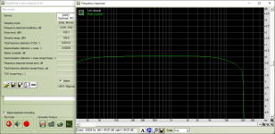
THD figures are again excellent, and DC offset is effectively zero, less than 1mV. However... this time there is a relatively huge HF roll-off (it was not there before modding), and the amp begins to heat up fast and dramatically as soon as I touch the power rails with the multimeter probe. It spontaneously does it on its own too sometimes, but this is a reliable way to trigger it.
Sorry to now dump more questions on you, but do you have any thoughts on what I may have done wrong or what may be going on? Is this similar to how your 980BX was behaving?
Thanks again!
Tom
Indeed! I had coloured those LTP resistors blue rather than red because I had not yet changed those, and I don't think I will.
This amp seems reasonably stable, but I haven't yet tried the capacitive load. In any case, as you suggested, nothing particularly exciting happened when I poked around in it.
As for sound, I'm not a huge fan of subjective descriptions, but since you asked, I would say that the amp has become clean and modern, and the best adjective I can find to describe it is "effortless". Whatever character it may have had has seeminlgy been neutralised and it's easy to forget that it's an integrated amp, not just an excellent power amp running straight off the DAC.
Now, the plot thickens. I left this amp be at this point because I jumped on a RA-971 Mk2 that came up on FB marketplare for a very good price, and immedately made the same mods. This time, things have not gone so well.
I have no idea what I did differently or if I did something wrong.
THD figures are again excellent, and DC offset is effectively zero, less than 1mV. However... this time there is a relatively huge HF roll-off (it was not there before modding), and the amp begins to heat up fast and dramatically as soon as I touch the power rails with the multimeter probe. It spontaneously does it on its own too sometimes, but this is a reliable way to trigger it.
Sorry to now dump more questions on you, but do you have any thoughts on what I may have done wrong or what may be going on? Is this similar to how your 980BX was behaving?
Thanks again!
Tom
Attachments
- Home
- Amplifiers
- Solid State
- Improve a Rotel amp THD by 20dB!