Hi Tom,
Well, you seem to have roll off at both ends.
Low end:
Did you increase the NFB 100uF capacitor C607 to 220uF?
High end:
I should have seen this on your schematic, sorry. You have run into the same problem I described in post #427. Shorting the input cap now makes the 12k connect directly to the 330pF HF cap C603, making a nice (but unwanted) 40kHz RC filter. Remove the 330p (or make it 100p), but make sure that the corresponding HF cap in the preamp's input is still in place - I think it is C503/4.
BTW, I also now see that you reduced the 3k3 R651 to 330R while keeping the 220pF - you could try to change back to 3k3.
As for the sudden heating up, that probably indicates instability. Did you put a scope on the output?
Long distance diagnosis is always difficult, I would first double check that both 47pF Miller caps are in their right places and securely soldered.
If the problem persists, you could try increase them to 56p.
Per
Thanks so much Per!!
FR sorted. And good eye! Yes, I had popped the 100uF back in to see if that was causing any of the problems.
I don't know what I did with the other one, since it doesn't have the same issue - did I not make the coupling mods? Did I take out the cap? I'll have to have a look.
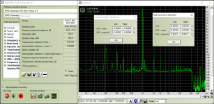
Anyway, pending scoping of the output (albeit with a very rudimentary USB scope), here's how the second unit is looking now.
Thanks again. It's really quite remarkable what's possible with this unit, and now that I have two of them, I'm even more tempted to try and take things further with the tranny addition.
Cheers,
Tom
FR sorted. And good eye! Yes, I had popped the 100uF back in to see if that was causing any of the problems.
I don't know what I did with the other one, since it doesn't have the same issue - did I not make the coupling mods? Did I take out the cap? I'll have to have a look.
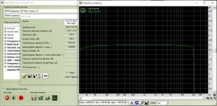
Anyway, pending scoping of the output (albeit with a very rudimentary USB scope), here's how the second unit is looking now.
Thanks again. It's really quite remarkable what's possible with this unit, and now that I have two of them, I'm even more tempted to try and take things further with the tranny addition.
Cheers,
Tom
Attachments
Hi Tom.
That looks better, although there is still something a bit strange with the roll-offs.
Which soundcard are you using - and did you obtain and use a calibration file for it?
I also see that it (or maybe the RightMark analyser) has a clear and sharp cutoff at 20kHz. That is probably done by using some high order filtering which can/will have some 'wobble' down in the pass band. So the closer to this cutoff you go, the less 'reliable' the measurement will become.

RA-971 APS measurements. Yellow and green traces before upgrade - blue and grey after.
I use XonarU7 with REW which perhaps isn't a perfect analyser setup - but a LOT cheaper than an Audio Precision device.💵💰
Again, the 50 and 100Hz peaks are probably more down to stray pickup by my measurement setup than real.
Actually, the ink on that point on my to-do list of 'pending instrument improvements' is actually fading away ......😳
Also note the slight 'wobble' down below 6Hz, but hey, try to measure those amplitudes with a standard generator and a DMM.
For the upper LP cutoff I do use a generator and a DMM on the output.
The frequency at which the ac amplitude has fallen below 0.707V of a 1V of a test signal is the upper -3dB point. On an upgraded 971 it is 185kHz.
Per
That looks better, although there is still something a bit strange with the roll-offs.
Which soundcard are you using - and did you obtain and use a calibration file for it?
I also see that it (or maybe the RightMark analyser) has a clear and sharp cutoff at 20kHz. That is probably done by using some high order filtering which can/will have some 'wobble' down in the pass band. So the closer to this cutoff you go, the less 'reliable' the measurement will become.
RA-971 APS measurements. Yellow and green traces before upgrade - blue and grey after.
I use XonarU7 with REW which perhaps isn't a perfect analyser setup - but a LOT cheaper than an Audio Precision device.💵💰
Again, the 50 and 100Hz peaks are probably more down to stray pickup by my measurement setup than real.
Actually, the ink on that point on my to-do list of 'pending instrument improvements' is actually fading away
......😳Also note the slight 'wobble' down below 6Hz, but hey, try to measure those amplitudes with a standard generator and a DMM.
For the upper LP cutoff I do use a generator and a DMM on the output.
The frequency at which the ac amplitude has fallen below 0.707V of a 1V of a test signal is the upper -3dB point. On an upgraded 971 it is 185kHz.
Per
The 971 does have a 10R / 100n Zobel
This is not Zobel, but RC SNUBBER.
Snubbers are frequently used in electrical systems with an inductive load where the sudden interruption of current flow leads to a large counter-electromotive force: a rise in voltage across the current switching device that opposes the change in current, in accordance with Faraday's law.
This is not Zobel, but RC SNUBBER.
And so speaketh the 1964 Oracle! Heed his all-knowing words you pitiful diyAudio ignorami.....or else!
It does make a poor 1954 mortal like me a bit concerned, though🤔..... does this mean that my Zobel Network is dead?
Or are these Zobel fat cats just munching away on a bowl of SNUBBERS?
🤣🤣🤣🤣🤣
In the spirit of contradiction and to bring a new theory, I would say that the big cats eat the old lady who was previously in the big cats' coat. 😀
I think you may well be right about that, just lend these cats a finger and ....

On the positive side, you will soon be inside a nice soft and warm Zobel coat! 😆🤣

OK, I'd better stop now.... No more Zobel (Sable, Cоболь, Martes Zibellina) cats for me! Promise!
I think I will put in a Boucherot Cell instead at the amp's output.😉😊
On the positive side, you will soon be inside a nice soft and warm Zobel coat! 😆🤣
OK, I'd better stop now.... No more Zobel (Sable, Cоболь, Martes Zibellina) cats for me! Promise!
I think I will put in a Boucherot Cell instead at the amp's output.😉😊
Last edited:
You know Sam, I actually liked it better when you posted in Cyrillic - that made it mush easier for us mortals to ignore and skip.
I could name a number of other official websites, books and blogs that has spent effort in explaining and defining this issue with regards to the RC (Zobel or Boucherot) circuit at the speaker output of an amp - or damping secondary resonance at a transformer output, etc.
But come to think of it, I think that it would simply be too cruel to direct a troll like you onto these other blogs.
Better to keep you here where we can pat your head when you have forgotten your theory and/or your pills.
Sorry, I am not this menacing by nature, but I do take offense to your "I know best" attitude and one-liners - particularly when what you claim is demonstrably wrong.
So could you please stop doing that on this thread?
Realy ?
Well, I may be wrong here. I barely scraped through my basic year of Latin.
I found it difficult to concentrate on a dead language while being surrounded by a bunch of very living young ladies in class.😊
I could name a number of other official websites, books and blogs that has spent effort in explaining and defining this issue with regards to the RC (Zobel or Boucherot) circuit at the speaker output of an amp - or damping secondary resonance at a transformer output, etc.
It’s a disaster if a shoemaker starts baking pies, and a pie maker starts making boots.
For example, posts 880, answer 881, and so on.
It’s certainly much more interesting than a dead language. 🤓I found it difficult to concentrate on a dead language while being surrounded by a bunch of very living young ladies in class.😊
I am a few years late to the party, but:
I have an old RA820, and providing it still works, then it could be an interesting winter project to perform similar mods to those documented for the RA820AX.
However the circuit board certainly looks different to the photos of the 820AX circuit board, even though some of the components look similar (eg the IC), but are in different locations (especially the power capacitors I think).
I can't find an RA820 circuit schematic on the web, so does anyone have one that they could post, before I progress any further?
Hi Magicm31,
I don't have a tech manual on the RA-820, and no, there are none on the web that I could find.
Actually I have avoided all the 'thin' versions of the 800 series mainly because their pcb's are clearly taped up by hand with components and jumpers in all directions - not very professionally IMHO. Any upgrade will be fiddly stuff.
You are thus facing the major task to actually re-draw the layout and schematic - and then deciding where possible upgrades could fit in. Quite some work unless someone comes forward with a manual.
Anyone?📢
@huggygood sadly it seems that hifi engine is not accepting new registrations. If you PM me maybe we can explore alternative ways to gain access to the schematic.
Thanks AngelP.Hi Magicm31,
I don't have a tech manual on the RA-820, and no, there are none on the web that I could find.
Actually I have avoided all the 'thin' versions of the 800 series mainly because their pcb's are clearly taped up by hand with components and jumpers in all directions - not very professionally IMHO. Any upgrade will be fiddly stuff.
You are thus facing the major task to actually re-draw the layout and schematic - and then deciding where possible upgrades could fit in. Quite some work unless someone comes forward with a manual.
Anyone?📢
As I read this thread I had gradually formed the realisation that the original PCBs were probably hand taped.
Yes I agree not professional, but that feels not very professional compared to where we are four decades later.
I hope that @huggygood can deliver with a schematic, but otherwise please PM me with ideas because it would be a pity to not try the improvements that you have documented in this thread.
- Home
- Amplifiers
- Solid State
- Improve a Rotel amp THD by 20dB!