Ok, here goes. TL/DR summary at the end. I attach below the asc file for the last mod stage, TMC, so you can easily modify it by removing stuff to get any of the previous ones. Note that to get a well-behaved FFT you need to make the input and feedback caps very large (hence their values), otherwise you get a "slanted" noise floor that may hide some of the harmonics. SR and overshoot were measured by changing the voltage source to a step and measuring on the resulting response. The 1.2 amplitude value was chosen to simulate ~30W/8ohm output (don't forget that in LTSpice the amplitude corresponds to Vpeak, so you have to do the numbers to convert from RMS).
Since we're dealing with many variables for the IPS, VAS and compensation schemes, these are just some of the many combinations that you can have, feel free to try your own modifying the attached files. Some of the choices I've made to keep the number of options manageable:
- As explained in post #188, I've left Rin = 47k and increased the feedback resistors to 47k/2k7 for DC balance.
- The 150p cap next to the lower driver is always in (except in the simulation of Per's mod). Removing it doesn't have a big impact on loop gain shape or THD.
- The CM degeneration resistors are 43R to get a voltage drop of 30mV. Self recommends 30-60mV in the context of discrete CMs; since I'm using dual matched pairs (2SC2291) I assume that it's safe to go with the lower value here.
- Rdeg for the differential pair are 330R which gives a typical 10:1 degeneration ratio as recommended by Cordell and others.
- I stick throughout with the original LTP tail current of ~1.4mA.
- In the stock non-UK version of the amplifier (the one I have), as well as the shunt VAS compensation there's a Cdom = 10p cap. In the early mod stages this is the one I adjust to keep a roll-off shape and UGF as close as possible to the original (post #193 above explains why I think this is a good idea).
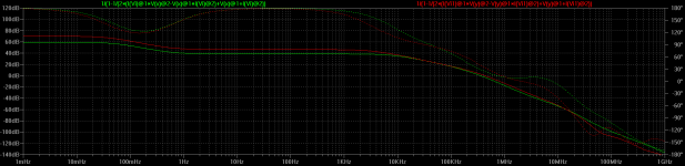
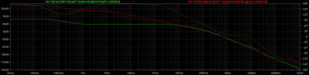
Here's a summary of the results and below plots of the loop gain of each stage vs. stock (please excuse the funny stage numbering):
- Stock:
PM = 29deg @ 355kHz, THD @ 1kHz = 0.00406%, SR = 9.5V/us, Overshoot = 4%
- Stage 1a: IPS CM load, 330R degeneration, Cdom = 15p, stock VAS load
PM = 34deg @ 428kHz, THD @ 1kHz = 0.00865%, SR = 9.5V/us, Overshoot = 7.4%
Twice the THD as stock, even though OLG @ 1kHz has increased by ~7dB? Hmm... After some head-scratching, I think what's going on is that the CM doesn't like the small voltage drop across it with the simple VAS: Vce for the left hand CM transistor is ~1V and it may like a higher voltage to work properly. Note that in fact current balance in the differential pair isn't any better than stock (offset is actually worse, ~25mV vs ~11mV). I could have played with Re in the VAS to increase the voltage drop but I didn't want to introduce another variable.
- Stage 1b: IPS Rload = 2k4, Cdom = 22p, EF-VAS, stock VAS load
PM = 28deg @ 355kHz, THD @ 1kHz = 0.00198%, SR = 9.3V/us, Overshoot = 3.4%
Note that to keep balance the Rload has to be increased to 2k4 to account for the extra Vbe drop. EF-VAS shows its benefits: half the stock THD.
- Stage 2: IPS CM load, 330R degeneration, Cdom = 15p, EF-VAS, stock VAS load
PM = 34deg @ 428kHz, THD @ 1kHz = 0.00096%, SR = 9.5V/us, Overshoot = 7.4%
Bingo: now adding CM load and degeneration to the EF-VAS gets us to 1/4th of the stock THD. Vce for the left hand CM transistor is now up by one Vbe to ~1.6V, as expected, differential pair current balance is significantly better (714/721uA vs. 741/694uA) and offset down from 11mV to -3.3mV, so it seems that the extra voltage is just what the CM needed to work optimally.
For all remaining stages, this combination of IPS+CM+degeneration and EF-VAS stays, stock VAS load is removed and only compensation varies:
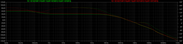
- Stage 3a: Miller-only comp., Cdom = 27p
PM = 46.7deg @ 448kHz, THD @ 1kHz = 0.00095%, SR = 19.8V/us, Overshoot = 8.9%
No significant change in THD, which is a bit strange since the load on the VAS is much lighter now. Maybe that's something that doesn't simulate well. We have twice the SR and although the PM is higher we also have more overshoot.
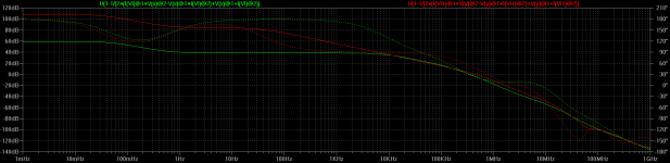
- Stage 3b: lead-lag comp., VAS load = 330p to ground and 220R + 560p to ground (as in Rotel RB-1050), Cdom = 22p
PM = 35.1deg @ 366kHz, THD @ 1kHz = 0.00096%, SR = 5.2V/us, Overshoot = 8.1%
I've taken the component values straight from the RB-1050 schematic and again adjusted Cdom, so it's more of a "hybrid" Miller + shunt + lead-lag compensation. THD is as good as Miller only, but this time half the SR as stock. Obviously we're throwing out of the window the SR advantage of the CM by making the poor VAS drag its feet.
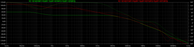
- Stage 3c: TPC, C1 = 330p, C2 = 33p, R = 2k2
PM = 28.5deg @ 378kHz, THD @ 1kHz = 0.00014%, SR = 19.6V/us, Overshoot = 27.9%
I went with C1 >> C2 because that's how Self does it and his reasons (lighter VAS load) are persuasive. THD down to 1/40th of stock, impressive, but the marginal PM and especially that worrying phase dip before reaching it could be the cause of the huge overshoot. Looks like stability could be *very* conditional here...
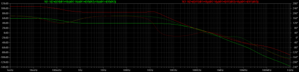
- Stage 3d: TMC, C1 = 47p, C2 = 470p, R = 2k2
PM = 45.2deg @ 390kHz, THD @ 1kHz = 0.00016%, SR = 18.7V/us, Overshoot = 1.2%
In this case I went with C1 << C2 after Cordell (for TMC Self uses C1 = C2), although his ratio is ~4:1 rather than the 10:1 I use here, but that's how I could match the stock roll-off best. Looks like we have a winner: equally impressive THD and similar SR as TPC but a much healthier PM and barely any overshoot. Note that this is despite having that same phase dip before UGF as TPC as you can see in the plot, so either my previous comment is incorrect or there's something else going on that makes the dip not matter as much (or not at all) with this arrangement. Note also how the loop gain departs from stock after the UGF. It looks like we're introducing zeros that may in fact be beneficial to compensate some of the HF poles, but it's up there where I'm cautious about trusting the simulation too much, so handle with care. Interesting also that Cordell claims that, unlike TPC, TMC doesn't introduce any peaking in the loop gain response: I do get it in simulation and in fact with TPC I don't get any, though I did with other cap values that I tried.
- Per's latest: CM, no degen, EF-VAS, Cdom = 100p, VAS load = 33p, 150p cap removed (I've left the tail biasing as stock for consistency with the other sims)
PM = 37.9deg @ 334kHz, THD @ 1kHz = 0.00048%, SR = 12.8V/us, Overshoot = 2.5%
Another winner here in all respects: 1/10th of stock THD (he got better THD+N results but don't forget that we're simulating different transistors here and he dealt with supply ripple as well), better SR, very little overshoot and, unlike all the others, tried and tested!
TL/DR summary: the usual disclaimers of simulation apply, more so in this case where we're using different transistors and a perfectly matched differential pair. The combination of CM load, degeneration and EF-VAS looks like a no-brainer: THD down to 1/4th even with the stock VAS loading, which if you replace with simple Miller comp (stage 3a) you get twice the SR and probably a further THD reduction that the simulation doesn't show for some reason. Lead-lag (stage 3b) looks like a step back, TPC (stage 3c) could be trouble stability-wise and TMC (stage 3d) looks too good to be true: 1/40th (!) the stock THD and excellent stability on paper, though things may be different in reality. Finally, if you want to play it safe rather than try your own thing, do what Per did (see post #119 for his latest version) and enjoy the "Blameless Rotel"! 😉
Cheers,
Cabirio
Since we're dealing with many variables for the IPS, VAS and compensation schemes, these are just some of the many combinations that you can have, feel free to try your own modifying the attached files. Some of the choices I've made to keep the number of options manageable:
- As explained in post #188, I've left Rin = 47k and increased the feedback resistors to 47k/2k7 for DC balance.
- The 150p cap next to the lower driver is always in (except in the simulation of Per's mod). Removing it doesn't have a big impact on loop gain shape or THD.
- The CM degeneration resistors are 43R to get a voltage drop of 30mV. Self recommends 30-60mV in the context of discrete CMs; since I'm using dual matched pairs (2SC2291) I assume that it's safe to go with the lower value here.
- Rdeg for the differential pair are 330R which gives a typical 10:1 degeneration ratio as recommended by Cordell and others.
- I stick throughout with the original LTP tail current of ~1.4mA.
- In the stock non-UK version of the amplifier (the one I have), as well as the shunt VAS compensation there's a Cdom = 10p cap. In the early mod stages this is the one I adjust to keep a roll-off shape and UGF as close as possible to the original (post #193 above explains why I think this is a good idea).
Here's a summary of the results and below plots of the loop gain of each stage vs. stock (please excuse the funny stage numbering):
- Stock:
PM = 29deg @ 355kHz, THD @ 1kHz = 0.00406%, SR = 9.5V/us, Overshoot = 4%
- Stage 1a: IPS CM load, 330R degeneration, Cdom = 15p, stock VAS load
PM = 34deg @ 428kHz, THD @ 1kHz = 0.00865%, SR = 9.5V/us, Overshoot = 7.4%
Twice the THD as stock, even though OLG @ 1kHz has increased by ~7dB? Hmm... After some head-scratching, I think what's going on is that the CM doesn't like the small voltage drop across it with the simple VAS: Vce for the left hand CM transistor is ~1V and it may like a higher voltage to work properly. Note that in fact current balance in the differential pair isn't any better than stock (offset is actually worse, ~25mV vs ~11mV). I could have played with Re in the VAS to increase the voltage drop but I didn't want to introduce another variable.
- Stage 1b: IPS Rload = 2k4, Cdom = 22p, EF-VAS, stock VAS load
PM = 28deg @ 355kHz, THD @ 1kHz = 0.00198%, SR = 9.3V/us, Overshoot = 3.4%
Note that to keep balance the Rload has to be increased to 2k4 to account for the extra Vbe drop. EF-VAS shows its benefits: half the stock THD.
- Stage 2: IPS CM load, 330R degeneration, Cdom = 15p, EF-VAS, stock VAS load
PM = 34deg @ 428kHz, THD @ 1kHz = 0.00096%, SR = 9.5V/us, Overshoot = 7.4%
Bingo: now adding CM load and degeneration to the EF-VAS gets us to 1/4th of the stock THD. Vce for the left hand CM transistor is now up by one Vbe to ~1.6V, as expected, differential pair current balance is significantly better (714/721uA vs. 741/694uA) and offset down from 11mV to -3.3mV, so it seems that the extra voltage is just what the CM needed to work optimally.
For all remaining stages, this combination of IPS+CM+degeneration and EF-VAS stays, stock VAS load is removed and only compensation varies:
- Stage 3a: Miller-only comp., Cdom = 27p
PM = 46.7deg @ 448kHz, THD @ 1kHz = 0.00095%, SR = 19.8V/us, Overshoot = 8.9%
No significant change in THD, which is a bit strange since the load on the VAS is much lighter now. Maybe that's something that doesn't simulate well. We have twice the SR and although the PM is higher we also have more overshoot.
- Stage 3b: lead-lag comp., VAS load = 330p to ground and 220R + 560p to ground (as in Rotel RB-1050), Cdom = 22p
PM = 35.1deg @ 366kHz, THD @ 1kHz = 0.00096%, SR = 5.2V/us, Overshoot = 8.1%
I've taken the component values straight from the RB-1050 schematic and again adjusted Cdom, so it's more of a "hybrid" Miller + shunt + lead-lag compensation. THD is as good as Miller only, but this time half the SR as stock. Obviously we're throwing out of the window the SR advantage of the CM by making the poor VAS drag its feet.
- Stage 3c: TPC, C1 = 330p, C2 = 33p, R = 2k2
PM = 28.5deg @ 378kHz, THD @ 1kHz = 0.00014%, SR = 19.6V/us, Overshoot = 27.9%
I went with C1 >> C2 because that's how Self does it and his reasons (lighter VAS load) are persuasive. THD down to 1/40th of stock, impressive, but the marginal PM and especially that worrying phase dip before reaching it could be the cause of the huge overshoot. Looks like stability could be *very* conditional here...
- Stage 3d: TMC, C1 = 47p, C2 = 470p, R = 2k2
PM = 45.2deg @ 390kHz, THD @ 1kHz = 0.00016%, SR = 18.7V/us, Overshoot = 1.2%
In this case I went with C1 << C2 after Cordell (for TMC Self uses C1 = C2), although his ratio is ~4:1 rather than the 10:1 I use here, but that's how I could match the stock roll-off best. Looks like we have a winner: equally impressive THD and similar SR as TPC but a much healthier PM and barely any overshoot. Note that this is despite having that same phase dip before UGF as TPC as you can see in the plot, so either my previous comment is incorrect or there's something else going on that makes the dip not matter as much (or not at all) with this arrangement. Note also how the loop gain departs from stock after the UGF. It looks like we're introducing zeros that may in fact be beneficial to compensate some of the HF poles, but it's up there where I'm cautious about trusting the simulation too much, so handle with care. Interesting also that Cordell claims that, unlike TPC, TMC doesn't introduce any peaking in the loop gain response: I do get it in simulation and in fact with TPC I don't get any, though I did with other cap values that I tried.
- Per's latest: CM, no degen, EF-VAS, Cdom = 100p, VAS load = 33p, 150p cap removed (I've left the tail biasing as stock for consistency with the other sims)
PM = 37.9deg @ 334kHz, THD @ 1kHz = 0.00048%, SR = 12.8V/us, Overshoot = 2.5%
Another winner here in all respects: 1/10th of stock THD (he got better THD+N results but don't forget that we're simulating different transistors here and he dealt with supply ripple as well), better SR, very little overshoot and, unlike all the others, tried and tested!
TL/DR summary: the usual disclaimers of simulation apply, more so in this case where we're using different transistors and a perfectly matched differential pair. The combination of CM load, degeneration and EF-VAS looks like a no-brainer: THD down to 1/4th even with the stock VAS loading, which if you replace with simple Miller comp (stage 3a) you get twice the SR and probably a further THD reduction that the simulation doesn't show for some reason. Lead-lag (stage 3b) looks like a step back, TPC (stage 3c) could be trouble stability-wise and TMC (stage 3d) looks too good to be true: 1/40th (!) the stock THD and excellent stability on paper, though things may be different in reality. Finally, if you want to play it safe rather than try your own thing, do what Per did (see post #119 for his latest version) and enjoy the "Blameless Rotel"! 😉
Cheers,
Cabirio
Attachments
-
Rotel-stage3d-thd.asc7.5 KB · Views: 180
-
 stage3d.png27.8 KB · Views: 168
 -
 stage3c.png28.1 KB · Views: 167
 -
 stage3b.png28.6 KB · Views: 733
 -
 stage3a.png28.3 KB · Views: 742
 -
 stage2.png28.3 KB · Views: 737
 -
 stage1b.png26.9 KB · Views: 750
 -
 stage1a.png28.2 KB · Views: 758
 -
 Per.png27.8 KB · Views: 200
Hello chaps, sorry for the silence, but I have been under heavy flak from our SW guys over the last two weeks to finish a truly stubborn hardware prototype. Delivered it yesterday!!!!
Which reminds me of one of my favourite quotes:
I love deadlines! Especially the swooshing sound they make as they pass by.😀
Anyway, many thanks to Cabirio for the exhaustive simulation work, very interesting results. I think that the first conclusion is that a two-stage Miller cap compensation is probably not advisable on an old Rotel with its surrounding component tolerances and a PCB design which was most probably taped up by hand in 2:1 on film as Chris described (which actually reminds me that in my first IC design the etch, dopants and metallisation patterns were all done in “cut and peel” red tape film. Anyone remember that?).
Whatever, a two-stage Miller solution is also a bit tricky to implement on the old amp PCB with regard to appearance, mechanical stability and airwire stray capacitances.
I am pleased that the Spice model run mirrors the measured real improvements on the Rotel RA-820AX, although you may note that it is a factor of ten away from reality. I never set out to design a brand new amp topology or even better the likes of Curtis, Cordell, Self & Co. My goal was to demonstrate that on a £40 budget it is possible to transform it into an amp for which you otherwise would have to fork out £1000's. And with the simulations and real world work done so far on this thread, I believe that we may have got down to the circuit improvements that gives the most “bang for the buck”:
I realise that not everyone would want to venture into all these mods, as some are quite fiddly.
But I really would wish for more diyaudio followers to get an option to try, achieve and hear the result, which I am listening to right now - as it is absolutely staggering. A completely different level of detail and speaker control.
So, if there is any interest, I was considering to have a set of SMD PCB circuit designs produced which for the modder would more or less mean simply replacing three legged transistors with new pop-in devices with the working improvement circuits onboard.
I got the current mirror sorted, moving on to the EF-VAS, are there any suggestions for a prime choice SMD VAS transistor?
Cheers,
Per
Which reminds me of one of my favourite quotes:
I love deadlines! Especially the swooshing sound they make as they pass by.😀
Anyway, many thanks to Cabirio for the exhaustive simulation work, very interesting results. I think that the first conclusion is that a two-stage Miller cap compensation is probably not advisable on an old Rotel with its surrounding component tolerances and a PCB design which was most probably taped up by hand in 2:1 on film as Chris described (which actually reminds me that in my first IC design the etch, dopants and metallisation patterns were all done in “cut and peel” red tape film. Anyone remember that?).
Whatever, a two-stage Miller solution is also a bit tricky to implement on the old amp PCB with regard to appearance, mechanical stability and airwire stray capacitances.
I am pleased that the Spice model run mirrors the measured real improvements on the Rotel RA-820AX, although you may note that it is a factor of ten away from reality. I never set out to design a brand new amp topology or even better the likes of Curtis, Cordell, Self & Co. My goal was to demonstrate that on a £40 budget it is possible to transform it into an amp for which you otherwise would have to fork out £1000's. And with the simulations and real world work done so far on this thread, I believe that we may have got down to the circuit improvements that gives the most “bang for the buck”:
- A well matched input transistor pair
- Current mirror in place of the single collector resistor,
- Add an EF stage to the VAS and
- Replace the Rotel VAS lag load with a simple Miller cap.
- Input and VAS stage supply filtering
- Cascoding the input current source
- Decent reservoir capacitors with separate (non-starpoint) return paths, and
- Replace E-core transformer with a good quality toroidal.
I realise that not everyone would want to venture into all these mods, as some are quite fiddly.
But I really would wish for more diyaudio followers to get an option to try, achieve and hear the result, which I am listening to right now - as it is absolutely staggering. A completely different level of detail and speaker control.
So, if there is any interest, I was considering to have a set of SMD PCB circuit designs produced which for the modder would more or less mean simply replacing three legged transistors with new pop-in devices with the working improvement circuits onboard.
I got the current mirror sorted, moving on to the EF-VAS, are there any suggestions for a prime choice SMD VAS transistor?
Cheers,
Per
Hi Per,
You've been very generous sharing the project with our members. Thank you for that! It lays out an intelligent approach were they could see the direction decisions much like anyone would consider. It isn't about only doing "the best" all the time. Reality does intrude. Your budget was reasonable, and that's what people need to see.
Anything you add to this is welcome. Thanks again Per!
-Chris
Hi everyone,
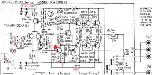
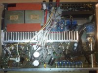
As I've currently taken up modding of the RA820BX2 again. The picture I've attatched shows the current state. A few more holes found their way into the amp for this, but this time it was the pcb's turn. Not shown are the Stage 1 mods (replacement of diodes D301-304 as per Per [whom I can't thank enough, btw ]) and the speaker protection circuit (that also protects the headphone-jack).
The red star is the position of the 10pF cap wich is missing from the BX2 (C611 here was a curious case of not beeing noted on the pcb but shortened itself to ground in the schematics - I ommitted it from the picture). Would the addition of this cap help stability?
Once Stage 2 (cascoding of Q603, here) is complete and I've got the zobel and inductor in, I'll post some pictures of the insides of the RA820BX2 - with all the "goodies" (stepped attenuator, speaker protection and its power supply, ventilation holes and the actual circuit-mods).
This might just become the "world's most ghetto" RA820BX2...ohh well...at least it's got the prettiest volume knob I could find 🙄.
I wonder if the amp thereby gets more "street-credibility" from the voodoo-audiophiles or not, because I didn't use non-magnetic "audio-grade"-parts throughout
In any case, I have learnt so much by modding, it was worth it. Thank you all and please excuse my spamming of Per's great thead with my stupid questions. But then again, this thread is so awesome, it deserves to be on page 1 😎
As I've currently taken up modding of the RA820BX2 again. The picture I've attatched shows the current state. A few more holes found their way into the amp for this, but this time it was the pcb's turn. Not shown are the Stage 1 mods (replacement of diodes D301-304 as per Per [whom I can't thank enough, btw
]) and the speaker protection circuit (that also protects the headphone-jack).The red star is the position of the 10pF cap wich is missing from the BX2 (C611 here was a curious case of not beeing noted on the pcb but shortened itself to ground in the schematics - I ommitted it from the picture). Would the addition of this cap help stability?
Once Stage 2 (cascoding of Q603, here) is complete and I've got the zobel and inductor in, I'll post some pictures of the insides of the RA820BX2 - with all the "goodies" (stepped attenuator, speaker protection and its power supply, ventilation holes and the actual circuit-mods).
This might just become the "world's most ghetto" RA820BX2...ohh well...at least it's got the prettiest volume knob I could find 🙄.
I wonder if the amp thereby gets more "street-credibility" from the voodoo-audiophiles or not, because I didn't use non-magnetic "audio-grade"-parts throughout
In any case, I have learnt so much by modding, it was worth it. Thank you all and please excuse my spamming of Per's great thead with my stupid questions. But then again, this thread is so awesome, it deserves to be on page 1 😎
Attachments
Hi again 1210,
Your "red star" cap PCB place is the for the Miller capacitor.
Rotel can't quite seem to decide whether it is necessary or not in their amp designs. I did try to put the 10pF in (before the mods) and found no change in stability - probably due to the already heavy Rotel compensation lag load on the VAS stage by C907, C909 and R623.
Once you get to modifying to the EF/VAS, the 100pF NPO Miller cap goes into that PCB place and the above three components go out. If you want further HF stability it would be better to add a R-C series between the bases of the Q601/5 input pair. The 330E/220pF values as used in RA-931 work well.
Cheers,
Per
Hi, cabirio.Ok, here goes.
You did a great job. But you're out of luck. It's not the best circuit design for the upgrade. The fact that the sound is make distortion on the upper frequencies of the audio range. The interference of higher frequencies gives the intermodulation noise on the lower frequencies. But decided not to simulate operation of the amplifier at the highest frequencies.
It is enough to apply carefully to these frequencies, and we'll see how much distortion and way to eliminate them. But it will be a completely different circuit design.
Attachments
A little update on my work-in-progress RA-840BX2 literally no one asked for.
Mods so far:
Still to do:
Is there any reason why it isn't recommended to only lower C609 from 390pF to 33pF as Per did in his mods but to remove it completely instead?
Is a a low-esr-type or a low-loss cap better as the 100µF cap in mod stage 1?
Mods so far:
- well matched input transistor pair
- VAS stage RC filter
- cascoded the input current source
- replaced back-to-back diodes at input current source as described in mod stage 1
- replaced single-turn bias-trimpots with multiturns
- new main supply caps (10mF), feedback caps (100µF bi-polar), input caps (5.6µF/150pF)
- 35A rectifier
- re-routed, non-starpoint grounding
- speaker protection relais + seperate supply
- stepped attenuator as volume control
- proper >250V AC switch capacitor
- balanced input+feedback resistors (470/15k)
- drilled ventilation holes above heatsink in chassis
- new rubber feet, twice the height of the originals
- offset from >20mV to 9.7mV (as predicted by cabirio)
- no on/off-thumps
- no channel imbalances whatsoever
- THD+N down from "why the f*** does this hum" to music
Still to do:
- 100pF Miller cap, replacing C907, C909 and R623
- green leds for power and speaker protection
- some paint
- zobel + inductor at output
- [phono-stage and phono power supply recap]
- [figure out how to replace the single collector resistor on the input pair with a current mirror]
- [replace noisy bando transformers with toroid and add fuse on primary...as is, there's just not enough space for a fuse
 ]
]
Is there any reason why it isn't recommended to only lower C609 from 390pF to 33pF as Per did in his mods but to remove it completely instead?
Is a a low-esr-type or a low-loss cap better as the 100µF cap in mod stage 1?
Great results, 1210!
The RA-820BX2 version is definitely more tricky to mod than the AX due to the compact PCB layout. I started a bit on my BX2, but put the project aside as I still have my beautiful modded RA-820AX playing. It does not cease to impress - whatever music or speakers you throw at it and I am truly amazed and chuffed with the result.
Now to your to-do list and questions:
Per
The RA-820BX2 version is definitely more tricky to mod than the AX due to the compact PCB layout. I started a bit on my BX2, but put the project aside as I still have my beautiful modded RA-820AX playing. It does not cease to impress - whatever music or speakers you throw at it and I am truly amazed and chuffed with the result.
Now to your to-do list and questions:
- You may get away with not putting the output inductor coils in - particularly if you are only powering your single speaker unit monsters. I actually skipped that step as it would also have meant a relocation of the Zobels - and there were already nice PCB holes and places for them in the AX. In the BX2 it would probably require mounting a separate PCB in the open space behind the heat sink?
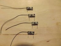
- I make the current mirrors on a SMT breadboard using a BCM61B and two 0.1% 100E 0603 resistors. All in a small format that allows the PCB pins to drop in place of the collector resistor and a thin wire to be wrapped or soldered to the (raised) collector leg on the other input transistor. I'll try to get a pic of the latest lot I made.
- Also, after some consideration I finally decided to skip the mains fuse once I was satisfied that everything was safe and in order on the mains input side.
- Yes, my VAS mod included replacing Q609 with a 33pF NPO
- I prefer to use Panasonic FM (aka Fantastic Magic) or Rubycon ZLG's for this – they have much lower esr than ordinary types at only slightly higher cost. Works as a “black hole” for ac noise – ok, maybe not quite that, but at least as a “very, very dark grey hole”😀
Per
Hi Per
 ,
,
As I don't know what the amp will be powering in the next decade or so, more protection does sound like a good idea. For the beasts/Viecher, it's not needed of course. The pcb-space I wanted to use for the inductor/resistor is the 0R22 output resistor outside of the feedback loop (wich would go out). This might either cause some smoke/oscillation (unlikely) or a little better damping factor and better HF-stability. I'm crossing my fingers for the latter.
As for the Zobels, that's another story. I have no clue where to put them.
I used 100µF/63V Panasonic FR series (same specs as FM, more voltage/capacity options and even longer life, but less fancy case - all for about the same price as FM) everywhere except the feedback, where 100µF/50V Nichicon Muse BPs have found their new home. Thanks for confirming that there's not much room for improvement. I have not yet used solid polymer caps anywhere, as they are ~10x more expensive and so far, the FRs worked superbly everywhere I didn't mis-use them.
Your current-mirrors look like they might like my amplifier...you've got your first customer pre-order/reservation
Greetings,
Ape-with-soldering-iron
I have tested my modded 820AX with a lot of different loads, including a serious 8 ohm // 2 uF and found no instabilities whatsoever, but that is of course not any guarantee.
Anyway, looking directly at the BX2 pcb layout - getting proper size coils in the crammed space of the R22 resistors will be a tight squeeze - but probably doable.
If you decide to do it, please consider to short the coils with 10 ohm damping resistors, you could even use a decent resistor body size as the coil former.
As for the Zobels, they need to go in before these coils, ie. closer to the output stage. There are some unused holes and space on the pcb to solder and maybe glue this RC combination down on both channels.
For the smd pcb's - stay tuned.
Per
I'm still a bit confused concerning the Miller compensation cap(s) mods. You said to leave VAS load C609 (C607 or your AX) 390pF out completely but in your mods you changed it for a 33pF one. Should I put the 33pF to ground in or leave them out?
In the meantime I aquired the 100pF (as well as the 33pF in question) 100V C0G/NP0 (same thing, unless I'm very much mistaken) capacitors and compact 2,5W (wirewound) 10R resistors for the zobel and inductor.
Greetings from the ape-with-soldering-iron
In the meantime I aquired the 100pF (as well as the 33pF in question) 100V C0G/NP0 (same thing, unless I'm very much mistaken) capacitors and compact 2,5W (wirewound) 10R resistors for the zobel and inductor.
Greetings from the ape-with-soldering-iron
Yes, replacing the 390pF C609/7 with a much smaller 33pF cap will reduce >10kHz distortion yet still obtain a dependable HF stability. According to Self this effect is purely empirical - but it is indeed confirmed by my own measurements on the 820AX.
Per
Per
The miller-update found its way into the amp. As did Zobels and inductors. And green LEDs. I've attatched a potato-quality-picture of my hackjob. And yes, the underside of the pcb is "just as pretty" 😛
First listening impressions: amp sounds drier/punchier/more controlled in the bass. Drums are a tad more "in your face". Or it's all imagination
I was too busy modding and I'm still unconvinced that humas can hear THD-changes <0.01%. They shure can't do that without a direct comparison, wich I didn't have.
Although I've modded quite a lot on this amp, the treble extension (input RF-quenching-cap was too big, killing treble), the stepped attenuator and the killing of the hummingbirds were definitly the most noticeable. Now the amp functions as an amplifier instead of a 50Hz-oscillator and the volume can be adjusted evenly for both channels. Very, very noticeable changes.
During this thread and my modding I learnt a lot about amplifiers. Thank you, everyone and especially Per , without whom this amp would still sit in a corner, unloved.
Now, the (last?) thing to do is to wait for the CM-pcbs to be available and meanwhile get a measurement-setup going to provide pretty graphs and numbers. Everyone loves those 😀
To quote a funny englishman:
"Great success!" - Borat
First listening impressions: amp sounds drier/punchier/more controlled in the bass. Drums are a tad more "in your face". Or it's all imagination
I was too busy modding and I'm still unconvinced that humas can hear THD-changes <0.01%. They shure can't do that without a direct comparison, wich I didn't have.
Although I've modded quite a lot on this amp, the treble extension (input RF-quenching-cap was too big, killing treble
), the stepped attenuator and the killing of the hummingbirds were definitly the most noticeable. Now the amp functions as an amplifier instead of a 50Hz-oscillator and the volume can be adjusted evenly for both channels. Very, very noticeable changes.During this thread and my modding I learnt a lot about amplifiers. Thank you, everyone and especially Per
, without whom this amp would still sit in a corner, unloved.Now, the (last?) thing to do is to wait for the CM-pcbs to be available and meanwhile get a measurement-setup going to provide pretty graphs and numbers. Everyone loves those 😀
To quote a funny englishman:
"Great success!" - Borat
Attachments
AngelP,
Thanks, this is a great thread. You inspired me to clean up another old Rotel that I've had on the shelf, an RB-970 BX mkII. Its sound always had a kind of guttural muddiness.
But surprise, surprise: a spice model of the circuit shows that it should be capable of -100db levels of distortion! So why does it sound bad? This amp has at least two obvious flaws in stock form:
- no rail filter for the amp input stages
- single ground star shared by charging currents and quiet grounds
It was pretty easy to fix those. I had to cut one trace per channel to add the rail filters. It sounds much cleaner now. I don't have equipment to measure THD. Maximum output is reduced by about a volt with 56R / 100uF rail filters. I included the first stage of the triple output stage behind the rail filter; it would have required more wiring not to.
This amp has an unusual input stage, with two long-tailed pairs per channel. It's fully symmetrical, if you look at the half of the input stage hanging off the positive rail and the negative rail, they are mirror images. I don't know if this kind of input stage has a name; it's not common AFAIK. My guess is that Rotel set it up this way to avoid turn-on and turn-off thumps so they could get away with no muting relay.
AngelP,
Thanks, this is a great thread. You inspired me to clean up another old Rotel that I've had on the shelf, an RB-970 BX mkII. Its sound always had a kind of guttural muddiness.
But surprise, surprise: a spice model of the circuit shows that it should be capable of -100db levels of distortion! So why does it sound bad?
Thank you for your comments, jpc.
To their defence, I think that generally the Rotels actually sound less "bad" than other amps in their price range - but yes indeed, they can be hugely improved through a modest budget and a bit (or rather quite a bit) of time and effort with a soldering iron.
Spice is a fantastic and powerful modelling tool, but it is just that. Cabirio did an absolutely sterling Spice job on the modded circuits, but the predicted distortion figures were still a factor ten away from reality. In any computer modelling, you only get out what you (or some programmer) has put in.
The RA-970 input circuit is really not that unusual, it is simply called a Double Differential Input Stage and it is as you say nicely symmetrical. Quite a few IC opamps use this configuration.
But, while going from a single input transistor amp design to a differential pair stage gave a very large performance improvement, doubling the amount of input transistors once again did not really do the trick for the 1970/80ies audio power amp designers. The main cause is that you now have at least four discrete low noise transistors to match for gain, bias and the lot. A clear sign of this is that the distortion specs for the RA-970 is still 0.03% - same as the earlier single diff input stage RA series amps.
The "muddiness" you describe was (as far as I recall) actually coined "The Smooth Rotel Sound" in the marketing material. I firmly believe that it is mainly caused by the consistent heavy VAS collector loading in all Rotels of this era. I have now modded a few RA-931 amps for friends and customers, and the consistent feedback is that they all have gladly traded this "smoothness" for the much improved detail and punch.
I enclose a pic (hopefully) showing that the mod now only involves removing a few components and replacing them with the drop in mod circuits. These are still hand made on protoboard, but I hope to get the time to have a batch of proper PCB's made up.
Cheers,
Per
Attachments

I actually had a RB980BX from the early 90's. I remember the typical Rotel sound and it was perhaps "muddy". But i think that was deliberate, just to give a feeling of "body" to the instrments.
I remember the schematic very well. It was a very basic "blameless" amp but with no linearising cap at the VAS. The level of NFB was almost linear up to around 20khz. Amps that sets the OLG with a capacitor has a sloping NFB that will subside upwards so the THD will incease over the entire audio range. This kind of amps usually sounds more bright since the THD rises with frequency. Most amps are made this way so the muddiness of Rotel may be a contrasting effect.
I sometimes have a suspicion that we are so used to bright sounding amps that we actually think this brightness is a sign of clarity. Personally, I prefer amps that makes you relax deeper in the sofa until you become one with the music. Some sort of zen experience, and then we don't wan't overly bright amps.
Don't you agree?
Svitjod
Indeed, that is the goal but it seems to be a moving target for me 🙂
AngelP or Per if you prefer, this is one of the most eye opening and entertaining threads on diyaudio. It's a real pleasure to see techs with real world experience troubleshoot right before our eyes. I have one question about projects like these:
How do you know which amps are not likely to be worth tweaking?
Hi nania,
Experience and the schematic. If the unit is built too cheaply, it isn't worth the effort no matter what the schematic looks like.
There are things I look for, and if they aren't there I'll pass on the job. Sometimes it's a tough call.
-Chris
Experience and the schematic. If the unit is built too cheaply, it isn't worth the effort no matter what the schematic looks like.
There are things I look for, and if they aren't there I'll pass on the job. Sometimes it's a tough call.
-Chris
- Home
- Amplifiers
- Solid State
- Improve a Rotel amp THD by 20dB!