I got one of these here, MKP 300V AC Y2/X1 type. My old 125V AC one is just dead, but not shortened (as a Y-type ought to, when abused as is was).
AFAIK it is only the cheap ceramic Y types that may short circuit at failure. The metallised film and paper types are self healing and should never short, see: http://www.kemet.com/Lists/Filestore/EvoxRifaRFIandSMD.pdf
Your Wima cap should be ok.
I'm a bit baffled by your bias-related THD-measurements. The 820BX2 is advertised as <0.08% THD at 30W / 8 ohms output. Your measurements seem to show that it's actually 20dB better than that in your setup. At what output level and with what load did you measure?
Yes, I also was a bit surprised and decided to look a bit further into it.
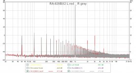
It turns up that by some strike of divine grace (probably including an accidental good input transistor pair hFE matching), the right channel does indeed have these nice low THD figures. However, the left channel measured a more "normal" 0.0341%, mostly caused by a large 3rd harmonic.
That commensurates with a perfect 0.1mVdc offset on the the right channel, while the left has over 3mV - still very good. But what the right channel has going for it on the 1kHz THD, it is very much the other way around on the 50Hz and harmonics noise, see the enclosed pic.
So, the amp will still have a large room for improvement by the relatively simple mods.
Having said that, I have now had a good look at the compact 820BX2's PCB, and it is definitely not as accommodating as the 820AX towards extra mod components. In particular, access to good ground traces is tricky and will involve quite some clever implementation and a few air wires.
Attachments
As I said elsewhere, I also have a Rotel RA-820AX and although it will be a while before I can get to it, I've already started with the planning phase so here are my initial thoughts for your perusal.
The general philosophy is not far from Per's wager: small changes that make a big difference. Aside from some more mundane things, like fixing the PCB star ground mess and adjusting some resistors for more reasonable preamp gain and better offset and noise, the first thing I've done is simulate the circuit in LTSpice and try a few tweaks to the IPS and VAS. Despite all the usual caveats of simulation vs. reality, I always find this very useful: just having to place and connect all the components gives you more familiarity with the circuit, and being able to play with it without anything going up in smoke makes it easier (at least for me) to understand how the circuit works.
At first I tried to find models for the specific transistors in the amp without much success. Then I considered building them according to Bob Cordell's painstaking method as described in his book (btw I just got it and it's excellent), but I was eager to get started so I thought I'd use some of the models he kindly provides in his web page and see what happens... Well, it "works" (i.e. simulates reasonably), and although it might in fact go up in smoke if you built it just like that, there are already things you can play with and see the effects in ways that, I hope (and I hope I'll be corrected by the experts if I'm wrong about this) will translate at least qualitatively to the real thing. The transistors I chose (based on one of Cordell's designs) are: 2N5551/2N5401, MJE243/MJE253, MJL21194/MJE21193. If there's anything completely off and/or you guys have better suggestions for models that will be closer to the real thing, I'd appreciate it.
Anyway, this is what I've learnt so far:
- Small variations of the IPS tail and load resistors (R607/R605) result in significant offset changes and, as expected, the sweet spot corresponds to the best balance between the collector currents (with balanced input and feedback resistors, which I plan to do). I wonder if, after matching the transistors as closely as possible, it might be worth fine-tuning these, perhaps use a temporary trim pot for R605 to find that sweet spot and then replace it with the required fixed value?
- IPS degeneration doesn't seem to do much but of course the simulation assumes perfect matching, so, any sugestions for tweaks of one of the transistors that will simulate a "realistic" mismatch? Which parameters would I have to change and by how much?
- EF VAS. Man, this is impressive! If I isolate the IPS and VAS with a simple class A output stage (as Self suggests in his book), I can get up a 5-fold reduction in THD without changing anything else (apart from the LTP load resistor, of course). I know OPS distortion will dominate and I won't be anywhere near such reduction, but still...
- What's with that 33k2 resistor (R623) loading the VAS collector? If I remove it and leave everything as it is, OLG increases by ~9dB and distortion goes down significantly, in fact in the isolated EF VAS case, that 5-fold reduction mentioned above turns into 16-fold (!). I don't see any changes in phase margin or anything else when I remove it, but it must be there for a reason, right? What am I missing?
- CM load + degeneration on the LTP is next on my list. I happen to have a couple of 2SC2291 matched pairs from an old Akai AM52 that could work beautifully here.
Sorry for the long post and many thanks in advance for any comments,
Cabirio
It may have been used to even out OLG across the audio band (same GBW, just less top gain), which is about the next best thing if you can't get distortion negligible altogether.- What's with that 33k2 resistor (R623) loading the VAS collector? If I remove it and leave everything as it is, OLG increases by ~9dB and distortion goes down significantly, in fact in the isolated EF VAS case, that 5-fold reduction mentioned above turns into 16-fold (!). I don't see any changes in phase margin or anything else when I remove it, but it must be there for a reason, right? What am I missing?
I guess you were simulating distortion at 1 kHz and possibly without a load? With an EF2 output, the effect of the resistor is probably going to be negligible once beta droop kicks in when driving 4 ohm loads at significant amplitudes.
Hi Cabirio,
Welcome to Rotel Modland.
Yes, there are sometimes significant differences between circuit simulation and reality, but I agree that LTSpice is a great “what if?” tool. Would you consider to share a copy of your 820AX .asc file?
Now to your questions:
R605 is an “el cheapo” solution for the VAS connection. A current mirror is much better, and the 820AX offers very good space for it. I will give the TL011 another try and hopefully get it to work (see post #119). If not, I could consider to have a batch of my own CM PCB design properly produced, if there is any interest from other modders. This small SMD PCB simply slots in place of the collector resistor (R605/6) with a thin lead to be soldered to the other (lifted) collector – dead easy!
Happy modding!
Per
Welcome to Rotel Modland.
Yes, there are sometimes significant differences between circuit simulation and reality, but I agree that LTSpice is a great “what if?” tool. Would you consider to share a copy of your 820AX .asc file?
Now to your questions:
- Small variations of the IPS tail and load resistors (R607/R605) result in significant offset changes and, as expected, the sweet spot corresponds to the best balance between the collector currents (with balanced input and feedback resistors, which I plan to do). I wonder if, after matching the transistors as closely as possible, it might be worth fine-tuning these, perhaps use a temporary trim pot for R605 to find that sweet spot and then replace it with the required fixed value?
- IPS degeneration doesn't seem to do much but of course the simulation assumes perfect matching, so, any sugestions for tweaks of one of the transistors that will simulate a "realistic" mismatch? Which parameters would I have to change and by how much?
R607 just sets the current through the input pair. I didn't see any dramatic changes in the measured offset when toying with this, but then that was after the matched transistor pair was put in and the DC base loads balanced. You could try to change one of the hFE values about 10%.
R605 is an “el cheapo” solution for the VAS connection. A current mirror is much better, and the 820AX offers very good space for it. I will give the TL011 another try and hopefully get it to work (see post #119). If not, I could consider to have a batch of my own CM PCB design properly produced, if there is any interest from other modders. This small SMD PCB simply slots in place of the collector resistor (R605/6) with a thin lead to be soldered to the other (lifted) collector – dead easy!
- EF VAS. Man, this is impressive! If I isolate the IPS and VAS with a simple class A output stage (as Self suggests in his book), I can get up a 5-fold reduction in THD without changing anything else (apart from the LTP load resistor, of course). I know OPS distortion will dominate and I won't be anywhere near such reduction, but still...
Indeed.
- What's with that 33k2 resistor (R623) loading the VAS collector? If I remove it and leave everything as it is, OLG increases by ~9dB and distortion goes down significantly, in fact in the isolated EF VAS case, that 5-fold reduction mentioned above turns into 16-fold (!). I don't see any changes in phase margin or anything else when I remove it, but it must be there for a reason, right? What am I missing?
The 33k resistor and the 330pF (plus the 150pF R609) collector loads are a Rotel standard brutal lag compensation design to quench any HF instability. I believe that this is one of the main design features that gives the “soft” Rotel sound. Some like it, some don't – I, for one, will never go back.
Happy modding!
Per
Thank you guys for your replies.
Re. the 33.2k resistor, indeed it flattens the OLG, but it doesn't seem to do much compensation-wise: the Bode plots pretty much merge at around 40kHz and from there upwards they are exactly the same, no difference at all in phase or gain margin, hence my head-scratching. Unless reducing OLG at low frequencies is A Good Thing in itself and I missed the memo...?
Offset: I guess it's the ratio between load and tail resistors that sets the balance and by playing with them I managed to bring the DC offset down to a few uV, but admittedly with their stock values (and balanced input and feedback Rs) it's only around 10mV and distortion didn't change signifficantly. Anyway the point is probably moot now because I've tried the CM + degeneration + EF VAS combo and I really like what I'm seeing.
Many thanks Per for your very kind offer but I've measured those 2SC2291s that I have and they are pretty well matched (297/298 and 327/328), I haven't found a complete datasheet but from what I see here it looks like they would work well, right? In the Akai AM52 where they came from they were used as cascodes in the IPS.
Right now I'm playing with that compensation and I've found a combination that looks good, again assuming that the simulation will translate at least loosely to the real thing. See attached the .asc file with the full works (CM, degeneration and EF VAS) and set up for phase and gain margin measurements
[*]. In the stock circuit I got 29deg (UGF around 350kHz) and 50dB, in this one I get 38deg (430kHz) and 32dB and the curves don't depart wildly from each other from around 20kHz upwards. As you can see the 330p cap and 33.2k R are out but the 150p cap is still in, I was just removing one thing at a time and adjusting Cdom and this is where I came upon this combination. Distortion is down from 0.004% to 0.00077%, offset is 1.7mV and slew rate is up from 9.5V/us to 18.5V/us.
Next on my list: try other compensation schemes, including your mod, Per (no degen, Cdom=100p, Cshunt=33p, 33.2k out, 150p out) and try playing with unbalanced LTP transistors. Watch this space!
Cheers,
Cabirio
[*] For those not familiar with this technique, here's the paper where I took it from and here's what you do: run the simulation, copy that long formula at the bottom, right-click in the plot panel, Add Trace, paste the formula in "Expression(s) to add", click OK and that's your Bode plot (strictly speaking there should be a minus sign at the beginning but this way you can read directly phase as phase margin, it saves you the tremendous effort of subtracting from 180 😀)
Edit: I can't for the life of me remember why I chose 43R resistors for the CM. R601 is the trim pot to adjust bias to ~18mA by making V(R629)=4mV. I adjusted it for you ;-)
Attachments
Last edited:
Hi Cabirio,
Thanks for the Spice file, and particularly thanks for the link to the J Green article. You would really wish for more uni lecturers of that calibre and general holistic view of engineering! i thoroughly enjoyed reading that paper!
I note that on the Spice sim you have increased the feedback to 47k, is that on purpose?
Also, I found that after the mods the 150p B-C cap could be safely eliminated with little effect on stability. Is there any reason that you kept it in?
Yup, quite a good and refreshing read, and his analysis of the poles and zeros in the Blameless is a real eye-opener.
I increased the feedback to from 8k2/470 to 47k/2k7 (same gain) for DC balance, just making Rinput = Rfeedback. I wanted to do something different here so I'm going to keep the opamp AC coupled (Wima MKS cap) and not touch the loading of the tone circuit, which is very sensitive to changes there. The small noise penalty is more than compensated for by replacing that big fat 33k/22k voltage divider for level-matching the tone bypass mode with 2k2/1k and the opamp 17k8/1k feedback with 1k/220R (I also wanted an input sensitivity of about 500mV rather than the stock 150mV). The load on the opamp is about 880R, no problem for the LM4562 that I plan to use here.
Re. the 150p cap, I just hadn't removed it yet... Even though you can do what you like in simulation, I try to proceed in a way not too different from what I would do in practice: one little step at a time, so this isn't necessarily my final scheme, it's still work in progress. It's true that from the point of view of compensation the 330p and 150p basically add up, so why not remove both, but then again why didn't they use a single 470p cap to ground in the first place? The fact that it goes to rail rather than ground and is placed close to Q617 on the PCB makes me wonder if it's there also for some local effect on that driver transistor... I've only seen something similar in Rod Elliott's P3A, but he doesn't explain what it does... Any ideas? Even though you have shown that it can be removed without problems and your results were outstanding, I want to approach this sort of pretending that "I haven't seen your mod" rather than jump straight to it, hopefully I'll learn more and have more fun that way, and right now I'm a bit reluctant to remove that virtual cap... ;-)
Cheers,
Cabirio
Question: How good can an old Rotel get? I have had dozens of Rotel amps through the repair workshop over the years, and this RA-802AX came in as a “speaker killer”. It turned out to be fully working – except it had a solid +16Vdc on both Left and Right speaker outputs. In a Rotel, the 12A rated power transistors and the 4A output “protection” fuses will easily deliver the resulting constant 2Adc into 8ohm speakers (even more into 4ohm), or 32W heat dissipation which indeed can destroy most static standing woofer coils. Finding the unusual fault involved a thorough circuit analysis – and in turn led us to discuss Rotel's power amp philosophy which has changed surprisingly little over the years. Then came the wager. I put on a bet that I could easily modify the Rotel amp design to improve the Total Harmonic Distortion (THD) from the 0.03% in the specs by a decade – (i.e. a factor of 10 or -20dB in audio terms) – transforming this “entry level” amp into an audiophile class of less than 0.003% THD. We even added three tough rules: 1. Fully reversible changes, i.e. no cutting of PCB tracks. 2. Budget: max GBP 40, i.e. faulty components could be replaced, but no upgrades to any fancy audiophile high-end components. 3. Preserve the “Rotel sound” i.e. no major changes of power amp audio signal path topology. In short, it was down to basic good audio engineering and circuit analysis. Ho Hum. We agreed that the changes should be staged and at first only applied to the Left channel, so we could follow the improvements through comparison RTA distortion measurements. If anyone is interested in whether such a dramatic reduction in Total Harmonic Distortion can be achieved, I will describe each stage and the THD improvements in subsequent posts.
I have a couple of Rotel RB-1050 please tell me what I need to do.
Hi cpc748,
This is a DIY site where you get to tell us what you did and how it worked out. This job was completed by a trained technician. If you are not working in the electronics business using a soldering iron, this is well beyond your capacity to complete.
There are thousands of little things a technician knows. Simple procedures for a technician are not simple for others not in the business. If you want this type of work done, you have to find a good audio technician and have them do it. If they get stuck, we try to answer specific questions. However, the trained people who answer these questions are taking time out of their day to give people a hand. Somehow asking one to explain the entire job, then troubleshooting any errors is way too much to ask.
So to answer your question, get the service information and plan out your work. If you can't, see someone who can and cover their time and parts.
-Chris
Hi cpc748,
This is a DIY site where you get to tell us what you did and how it worked out. This job was completed by a trained technician. If you are not working in the electronics business using a soldering iron, this is well beyond your capacity to complete.
There are thousands of little things a technician knows. Simple procedures for a technician are not simple for others not in the business. If you want this type of work done, you have to find a good audio technician and have them do it. If they get stuck, we try to answer specific questions. However, the trained people who answer these questions are taking time out of their day to give people a hand. Somehow asking one to explain the entire job, then troubleshooting any errors is way too much to ask.
So to answer your question, get the service information and plan out your work. If you can't, see someone who can and cover their time and parts.
-Chris
Thanks.
I'm pretty good with a soldering iron and was hopping someone would give me a few tips.
Hi cpc748,
Okay, now we're getting somewhere.
Start a new thread with your intention as the title. Post the schematics if you have them. Then look at specifics.
You might actually find your answers in other posts if you do a search. It's amazing what gems are contained in these threads. Use that as a jumping off point.
-Chris
Update: first of all I have simulated Per's mod and, not that I had any doubt of course, but obviously someone knew what he was doing: PM 38deg @ 330kHz, GM a healthy 34dB, SR 12.9V/us and THD down to 0.00048%. And the Bode plot actually follows the stock one even more closely than my scheme, only departing significantly at around 30-40MHz, but I wouldn't trust the simulation too much up there anyway, especially considering that it's using different transistors. Attached are two Bode plot pairs: stock vs. your compensation and stock vs. mine (as it was in the asc file I posted), phase not shown for clarity.
I think I should elaborate a bit on why I think that staying close to the stock Bode plot is a good idea. In general compensation will define the roll-off shape before the higher frequency poles (those due to device parasitics) have had a chance to introduce too much phase shift. We know that the simulation isn't accurate, and even less so in this case because it uses different transistors, so the absolute PM value that you get may be meaningless, but you can expect that, if two simulated compensation schemes have similar roll-off shapes and PMs, they will also be similar in reality. I assume that the designers of the amplifier took into account the actual transistors, operating conditions, PCB layout, etc. and optimized the compensation accordinglty, so sticking as closely as possible to it seems to be a safer bet than doing something radically different.
I've been playing with unbalanced betas in the LTP and there's no significant effect on distortion. Iirc (I can't find it now) Self states that the problem isn't beta but Vbe imbalance, and I'm not sure which parameters I should tweak to simulate it. In any case degeneration will certanily improve things (he measures a 10-fold THD reduction with just 2:1 deg. ratio) so I think I'll keep it.
As for that 150p cap, after re-reading Self on "Stability and VAS-collector-to-ground capacitance" it seems that there should be no harm in keeping it, although he claims he's never used more than 33p, apparently even higher values (280-480p) have little impact on distortion, so, since I'm doing something different that hasn't been tried and tested, I think I'll play it safe and keep it, at least initially.
Just for fun I'm playing with two-pole compensation now. Per, it's interesting because your scheme from post #105 gives a PM of 40deg, but before that the phase drops to a minimum of 38deg @ ~25kHz where gain is still 28dB, which may be the cause of the stability problem you had? OTOH reversing the caps cures this: no response peak and phase decreases smoothly to an even better 47deg PM, but you said you tried it reversed too, right?
Cheers,
Cabirio
Attachments

I have a couple of Rotel RB-1050 please tell me what I need to do.
Hi cpc748,
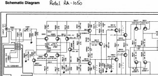
I must admit that I have never had a RA-1050 under the soldering iron, but I managed to have a look at the schematic last night. This amp sports a dual differential input stage (as some of the earlier BX2 types), which means double work at all stages (for starters it requires you to find and put in 4 matched PNP/NPN input transistor pairs).
But really, you could start to apply all the mod stages I have described for the 820AX, taking care to get the right transistor polarity in each place.
There may be a few special issues, like the clipping indicator, etc., but when you get to that point there will most probably be help to find here on diyaudio.
Cheers,
Per
Hi Cabirio,
Matched LTPs really make a large difference. Beta is the most important parameter. These matched in beta will have Vbe close anyway. Mismatched Vbe will affect your DC offset by the amount of difference. In short, a few mV. Matching beta greatly affects the differentiating between distortion and signal. Beta mismatch will also create some instability of DC offset as the amplifiers parts as they warm up. Finally, matching is all well and good, but they also need to be at the same temperature too. I use a touch of heat sink grease and heat shrink tubing to both hold them together, and to break the influence of ambient temperatures and currents. You may also find some critical pairs with caps on top as well.
I know that Doug Self and I disagree on this point, but all my experience matching parts show this point to be a valid one. Maybe it doesn't simulate that way, but it does in the real world. Doug has probably witnessed cases where the Vbe drops matter. I look at both and get matches so tight that tolerance on degeneration resistors becomes important.
-Chris
Hola Cabirio.
That is great simulation work! Yes, I did try reversing the capacitors in the two pole Miller setup, and got instability in both positions.
Out of interest, as I didn't try that, what if we took the central 2k resistor to the output node instead of V-?
You may also be interested in the RA-1050 schematic, sort of "what did Rotel do next?". The VAS load resistor is gone, replaced with a lead-lag R-C series load to V-. And the 150pF driver B-C cap is also gone - although they apparently kept PCB space open for the "old" compensation components.
Could there have been some interesting company internal discussions or disagreements??
Per
Attachments
@Chris: I'm pretty sure that an accurate simulation of a mismatch involves more than just changing one parameter in the model and that's why it makes little difference: you're obviously never going to find two transistors where everything is exactly the same except beta. Come to think of it, I may try to find two different models for the same transistor and see if that gives more plausible results.
I've just measured a bunch of 2SA970s that I have and are often quoted as a good alternative to 1016s. I've found two very good matches (258/258 and 307/308), so if I don't find better among the stock ones, I can always use those, and I'll couple them as you suggest.
@Per: Sure I'll be more than happy to add some fuel to the TMC fire! 😉 You're right that the evolution from the 820AX to the 1050 is very interesting and, as long as we're trying stuff, let's see what we can do with some tastefully applied lead-lag...
I must confess that at this point I have about a dozen LTSpice files with as many combinations of different IPS, VAS and compensation schemes and it's getting out of hand. Time to be systematic and do what I intended to do before I got carried away, i.e. proceed in simulation as I would when doing the actual mods: start from stock, make one change, check stability, measure distortion, another change, rinse and repeat... I'll report back with some numbers, plots and asc files for you ladies and gentlemen to peruse. Watch this space!
Cabirio
Hi Cabirio,
To me, spice is something you normally find in a bottle or bag. Everything I do is real time and real devices, and with real smoke if I mess up. I haven't a clue about spice models except to understand that spice assumes perfect transistor matches between the same type. Totally unrealistic.
I match transistors extremely tightly in a jig that takes into account all the parameters and match them at the test current closest to where they will actually run at. The circuit is merely a long tailed pair with an active current source / sink and I match by the difference across the collectors (or drains). The test resistors are 0.1% 100R units that I bought for this application. The presort is done with beta measurements attempting to maintain a constant temperature during the presort.
With this level of matching, the degeneration resistors have to be matched as well or it will throw out the balance. Vbe differences are typically only a few mV out. It has very little effect on things compared to the beta matching it would seem. I've been matching beta for well over 20 years now, getting better as time went on. I suspect that if the beta readings are very close, so will the Vbe readings. I could easily be wrong about that since what I am doing works so well that I have not investigated looking at Vbe drops. I can match at tail currents from 100 uA to 20 mA +. That covers pretty much everything you would normally see I would think.
-Chris
Well Chris, I do find simulation very useful and it helps me a lot in understanding how and why things work the way they do and bridging the gap between theory and reality. I'm all for learning by doing too and it's not that I'm afraid of the smoke, but to be honest I don't see much of a learning oportunity in "let's turn this into Self Ch. 6 Fig. 6.1.3a. Oops, it blew up. Ok, let's fix it and try fig. 6.1.3b instead...". Good for you if you can go straight from theory to cutting PCB traces, I just don't have the knowledge and expertise, it's much easier for me to see in simulation what different changes do to the poles, zeros, PM, etc. than to figure it all out in my head. And I really appreciate the knowledge and expertise that you and others share so generously here: case in point, when it comes to matching (which I'm well aware is one big limitation of LTSpice, or rather of the models available), I take good note of what you say and as I said I will use those well matched 970s if I don't find better ones among the stock 1016s, and of course I'll measure distortion before and after to see the effect it has (substantial, I'm sure). As for building a very accurate matching jig, it seems to me a bit overkill for this project whose main purpose is to learn and have fun, and it's not like I have a dozen more amplifiers queuing up where I could use it.
Btw, important tip for anyone reading this, pay careful attention to what Chris says about temperature: you simply cannot pick up a transistor, put it in the component tester, note the beta and go for the next one. Those three seconds that you held it between your fingers warmed it up enough to affect beta significantly. Visibly, in fact: once you've put it in the tester, just wait and watch the reading go down as the temperature drops. Be patient and wait until you get a stable reading. It will take a couple of minutes, during which you should stay still and not breathe too heavily, seriously! Just for fun blow very lightly on the transistor and see the reading change: it is that sensitive.
Anyway, I did try using two different models for the same transistor, I found another 2N5401, adjusted a bit some parameters that were way off (in some cases by orders of magnitude) and gave it a try. No cigar: THD actually went down slightly... Obviously it's not a matter of altering parameters randomly here and there, they are all connected and, for the model to be reasonably realistic, you would have to work out suitable equations connecting them and alter them "in sync", so to say. I won't bother because there are many other sources of distortion and things that do simulate well, so I leave it as an exercise for the reader: if someone does do it, I and I'm sure many others would really appreciate it. In the meantime I'll carry on simulating with my perfectly matched model. Results coming up soon.
Cheers,
Cabirio
Hi Cabirio,
Thank you.
You're the lucky one. I grew up with paper and pencil. Sometime later, stencils became available for PCB layout. Schematic capture was a big change for me. I only know how to do this because it was required to do the work. Professionals used 2X scale with rub-down transfers. I learned to do that too, and replicate boards using artwork on clear plastic exposed to UV light. An awful lot of work went into the simple PCBs even. So you are a part of the lucky generation who can use computers for this. Maybe some day I will be able to do as you do. I am laying out boards using Diptrace, which I really like using. Still getting the hang of going from a schematic capture to the PCB layout with those funny un-routed lines. Being able to print the PCB patterns to transfer onto PCB blanks is very "freeing". A real time saver for someone whose eyes are going bad with age.
-Chris

- Home
- Amplifiers
- Solid State
- Improve a Rotel amp THD by 20dB!