It is not me who is seeking to change facts. I have no agenda other than correcting error.wiseoldtech said:You simply cannot change fundamental electronic facts to suit your agenda, or pacify your beliefs.
As I said, you either slept through some of it or your teachers were confused. You choose which explanation you prefer. Despite an ID proclaiming yourself to be a Wise Old Tech you have made a number of false statements about fairly basic electronics. This is not esoteric stuff, where there may be room for argument; this is basic stuff which is either right or wrong.I prefer on not arguing on here about things that are credible facts derived from proper schooling, or listening to remarks that my instructors of such schooling are incompetent idiots.
I was educated long before the internet came along, in classrooms, with textbooks and highly regarded instructors, in accredited institutions.
From the fundamental elements of learning Ohm's Laws, up to 1990's technology.
I also went to various manufacturers Training Academy Sessions regarding specifics on their line of product servicing. (Sylvania/ECG, Magnavox, RCA, etc.)
That we can agree on.Nevertheless, I see online, a substantial amount of misguided information, popular beliefs, and obvious misunderstandings about things.
Yes. It has been considered, and we have presented the consensus view:KCHANG said:I thought that this issue must have been considered, and there must have been a consensus reached, as people have been building solid state amps for half a century by now.
1. you don't want any distortion here, as the loop will not correct it
2. with a big enough cap you will get vanishingly small distortion (alternatively you can use a smaller cap but then you have to use a linear cap and accept some LF rolloff)
That's what I understood. Am I misunderstanding Rod here: Distortion and Feedback
"Also notable is that any signal that is created within the feedback loop (most commonly noise) is also cancelled by global feedback. Because this generates signals that did not exist at the input, the error amplifier 'sees' any such extraneous signal as a deviation from the input signal, and cancels it to the best of its abilities. Note that input device noise is not cancelled, because the error amplifier cannot differentiate between noise it has created and the input signal"
This is how I understood it. It would be a simple matter to inject a signal into various parts of the amplifier and see how it is treated at the output.
That's what I understood. Am I misunderstanding Rod here: Distortion and Feedback
"Also notable is that any signal that is created within the feedback loop (most commonly noise) is also cancelled by global feedback. Because this generates signals that did not exist at the input, the error amplifier 'sees' any such extraneous signal as a deviation from the input signal, and cancels it to the best of its abilities. Note that input device noise is not cancelled, because the error amplifier cannot differentiate between noise it has created and the input signal"
That is correct if you assume that the feedback signal is an accurate sample of the output signal. Then anything within the loop is cancelled.
But if the feedback network itself distorts, if it does not present an accurate sample of Vout to the summing point, obviously the correction is also not correct and distortion will be created.
Jan
Thanks for confirming what I knew 😉 When I read this:That is correct if you assume that the feedback signal is an accurate sample of the output signal. Then anything within the loop is cancelled.
But if the feedback network itself distorts, if it does not present an accurate sample of Vout to the summing point, obviously the correction is also not correct and distortion will be created.
Jan
And then what Rod wrote I was a bit concerned 🙂 When they use the term loop they aren't including the feedback network (I'm hoping 😉)I am very serious, I sold it now, but I had a super nice power amp of 100 watts with 0.001%thd. Change the feedback amount by 1%, you will hear the difference, change anything inside a feedback loop (well designed) of over 22db, you wont hear anything, because it is precisely the function of the loop to correct any component deviation in the audible frequencies.
This is not true either. Also, NFB does not cancel it reduces. It is a ratiometric process not a subtractive process.That is correct if you assume that the feedback signal is an accurate sample of the output signal. Then anything within the loop is cancelled.
NFB does not cancel it reduces. It is a ratiometric process not a subtractive process.
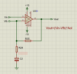
Of course it does not cancel, agreed. What is subtractive is the input stage which effectively amplifies the difference between Vin and Vfeedback.
I think we are on the same sheet.
Jan
NFB does not cancel it reduces. It is a ratiometric process not a subtractive process.
How this is eaxctly achieved is a most interesting question.Of course it does not cancel, agreed. What is subtractive is the input stage which effectively amplifies the difference between Vin and Vfeedback.
The DC-blocking feedback capacitor is in the signal path, but it's distortion is not reduced by feedback
Why? (the closed loop is one system, no matter the distortion inside the system it will self stabilize, the non-linearity can be anywhere in the path it doesn't matter below the reaction time, maybe at 50khz it can fail to correct, but with a proper bd of like 500khz the imperfection in the feedback resistor as well as the DC blocking caps will be part of the self correction)
Why does a capacitor 'quality' matters? The caps are doing their purpose to stop the DC signal and let a high bandwidth AC signal going through. What is the use of using a muse, blackgate, film cap? it makes no sense.
if the cap has a higher dissipation factor, which is still negligible, well the feedback is already divided... so it wont cause any issues, so a cheap normal cap should make no difference, same with wires...
The DC-blocking feedback capacitor is in the signal path, but it's distortion is not reduced by feedback
Why? (the closed loop is one system, no matter the distortion inside the system it will self stabilize, the non-linearity can be anywhere in the path it doesn't matter below the reaction time, maybe at 50khz it can fail to correct, but with a proper bd of like 500khz the imperfection in the feedback resistor as well as the DC blocking caps will be part of the self correction)
That capacitor is a component in the voltage divider that determines the signal fed back to the error amplifier stage. It is not "in the loop" itself. Same for the feedback resistors. A 1% error in a feedback component will cause a 1% error in the output, no correction. The fact that the ratio of the resistors sets the nfb gain should be a clue that these parts are not "in the loop" and subject to correction. Just the contrary, they determine the performance of the amplifier.
Derive the formula for a nfb amplifier, including the imperfect amplifier, and then let the "open loop" amplifier gain be arbitrarily large enough to be a negligible factor in the formula. The overall amplifier characteristics are then determined solely by the components in the feedback divider (to that degree of approximation), and if those components are imperfect, then so is the amplifier performance.
This is why thermal distortion in the nfb resistors can cause problems, unless dealt with by using all identical resistors of the same value to make the desired gain. For example, 1k to ground, and nine 1k in series (for a composite 9k resistor), for a nfb gain of ten in the usual non-inverting topology.
Last edited:
Might as well replace it with a 1N4007, it's cheaper than an electrolytic cap.the importance of this capacitor in a solid state amp is 0. Makes no difference at all audible or measurable.
I started off with TTL and there's a fan-out limit due to the available current on the output and the current a gate input takes. There was lots of current flow around. If you ran something a few minutes and there was a cold chip, you knew it wasn't working.Then I agree.
I came to think of digital electronics: Take a simple AND-gate; how many think of current flow looking at the symbol?
True, and sometimes it´s done on purpose.😱That is correct if you assume that the feedback signal is an accurate sample of the output signal. Then anything within the loop is cancelled.
But if the feedback network itself distorts, if it does not present an accurate sample of Vout to the summing point, obviously the correction is also not correct and distortion will be created.
Jan
Check the revered Tube Screamer distortion pedal.
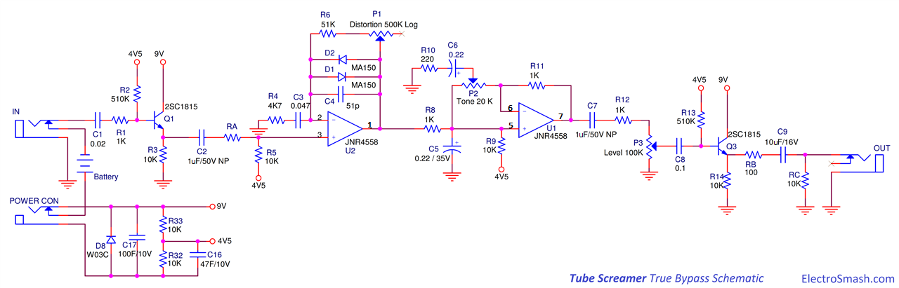
Notice:
* diodes D1/D2 in the NFB Loop 😱 are non linear as a function of applied voltage, and what Jan says above applies to a t.
* small world, also the capacitor C3 in the NFB loop has a HUGE effect on response, contradicting somebody who said it was irrelevant.
Won´t even search back, cut and paste, waste of good (electronick) ink and paper, a.k.a. bandwidth and storage space.
* poor Op Amp U2 , half of a 4558, is just doing its job of comparing/substracting Input and NFB signals and sending error signal to its own gain stage.
* just let´s repeat it once more, for the benefit of those who "don´t get it":
The Op Amp output signal is a function of: Input signal plus a sample of the output signal which is affected by the NFB network.
We have 3 actors in this plot. 😀
Which ... ummm ... includes the
DC-blocking feedback capacitor
It pays to listen to the wise old tech
Actually you clear up a few points correctly for me. The input signal is generally injected into the non-inverting input. Any extraneous signals across the capacitor are injected into the inverting input. Both signals are amplified by the same gain. However, the level of the extraneous signals is much much lower than the input signal. It's a double whammy. The feedback signal is already low, and any distortion generated by the capacitor is going to be a fraction of the feedback signal.
It always pays to listen to the wise old tech sitting at the back of the workshop.
And that's ok
Actually you clear up a few points correctly for me. The input signal is generally injected into the non-inverting input. Any extraneous signals across the capacitor are injected into the inverting input. Both signals are amplified by the same gain. However, the level of the extraneous signals is much much lower than the input signal. It's a double whammy. The feedback signal is already low, and any distortion generated by the capacitor is going to be a fraction of the feedback signal.
It always pays to listen to the wise old tech sitting at the back of the workshop.
My issue is what is the distortion that the capacitor generates with the low signal? Why would the signal be distorted if it passes through the capacitor???
If there is a quality factor, what is it? this is a feedback part, not some no feedback coupling capacitors, or should we start cap rolling, yea...no.
If there is a quality factor, what is it? this is a feedback part, not some no feedback coupling capacitors, or should we start cap rolling, yea...no.
Very nice Jonathan, I learned something today!
That trick is very old.
It is less often seen in BJT power amps because that "high-value resistor" makes embarrassing DC offset.
Back to Black.
A good, though dense, understanding of the difference between "the amplifier" and "the NBF network" can be gleaned from Black's early and later writings on negative feedback.
Harold Stephen Black - Wikipedia
His problem was that straight amplifiers *varied in gain* with every part in them, every tube replacement, battery/line droop, temperature....
He realized that a an amplifier with a gain not stable, but "high", could be combined with a NFB network to give gain depending on only two/few NFB network parts.
So you could build amplifiers with +/-20% resistors, +/-40% tubes, out in the cold/heat, and use two 1% resistors to get nearly 1% accuracy of gain.
The point was: a transcontinental telephone line had hundreds of amplifiers. If they varied only 0.1dB, the sum error on a long line could be dozens of dB, either way, not even consistent day to day. With NFB amplifiers the gain would be stable. Without tons of selected tubes, precision resistors, battery regulators, or temperature control.
In a high-NFB amplifier, NOT subjected to audiophile scrutiny, the signal transfer function is "only" about the NFB network. As we recognize every time we write the gain of an audio amp by looking at the NFB network.
I'm not sure that a polar e-cap of ample size is "bad". However the thread started about low-price Asian goods. China can make as bad or as good as you want to pay for, the bulk of buyers look only at price, so there are sure to be some crappy caps.
That capacitor is a component in the voltage divider that determines the signal fed back to the error amplifier stage. It is not "in the loop" itself. Same for the feedback resistors. A 1% error in a feedback component will cause a 1% error in the output, no correction. The fact that the ratio of the resistors sets the nfb gain should be a clue that these parts are not "in the loop" and subject to correction. Just the contrary, they determine the performance of the amplifier.
Derive the formula for a nfb amplifier, including the imperfect amplifier, and then let the "open loop" amplifier gain be arbitrarily large enough to be a negligible factor in the formula. The overall amplifier characteristics are then determined solely by the components in the feedback divider (to that degree of approximation), and if those components are imperfect, then so is the amplifier performance.
This is why thermal distortion in the nfb resistors can cause problems, unless dealt with by using all identical resistors of the same value to make the desired gain. For example, 1k to ground, and nine 1k in series (for a composite 9k resistor), for a nfb gain of ten in the usual non-inverting topology.
+1. This is probably the 4th or 5th time this is explained here. I think people just don't read posts, only regurgitate their (erroneous) opinion.
Jan
Always use a tantalum cap in the fbl. You can never use enough tantrums I have 20 in my gainclone.
Actually you clear up a few points correctly for me. The input signal is generally injected into the non-inverting input. Any extraneous signals across the capacitor are injected into the inverting input. Both signals are amplified by the same gain. However, the level of the extraneous signals is much much lower than the input signal. It's a double whammy. The feedback signal is already low, and any distortion generated by the capacitor is going to be a fraction of the feedback signal.
Yes and no. You must realize that that minuscule extraneous signal is amplified by the full open loop gain of the amplifier! So even if the error is just 10uV, and the open loop gain is say 60dB, it causes a 10mV error at the output. If the output signal is 10V, that's 0.1% distortion right there, and nothing you do to the amp will improve that.
It always pays to listen to the wise old tech sitting at the back of the workshop.
Only when they makes sense, which they sometimes do, sometimes not. Just like us. ;-).
Jan
Attachments
Last edited:
One thing to mention about breaking in a tantulum is good. throw it in a freezer first. Cryo treat it.
- Home
- Amplifiers
- Solid State
- Importance of the quality of the DC-blocking feedback capacitor?