
Correct, think of the cab in aerodynamic shapes, so as it goes round the 'bend' it has to 'cling' to 'something' for a bit to smooth out the otherwise abrupt acoustic impedance mismatch between the two boundaries [reflective boundary Vs free air].
Kind of surprised Olson didn't include this in his seminal paper posted earlier: https://p10hifi.net/tlinespeakers/forum/olson-baffleshape-fr.gif
Kind of surprised Olson didn't include this in his seminal paper posted earlier: https://p10hifi.net/tlinespeakers/forum/olson-baffleshape-fr.gif
Because I don't think laminar flow is what he was discussing, but diffraction. You can get a exotic as you want, but it turns out a 1/2 inch radius on a box does very well.Correct, think of the cab in aerodynamic shapes, so as it goes round the 'bend' it has to 'cling' to 'something' for a bit to smooth out the otherwise abrupt acoustic impedance mismatch between the two boundaries [reflective boundary Vs free air].
Kind of surprised Olson didn't include this in his seminal paper posted earlier: https://p10hifi.net/tlinespeakers/forum/olson-baffleshape-fr.gif
But only at very high frequencies. It has been shown that the equivalent of 3-4” is necessary to reduce problems down into the midrange.
dave
dave
I was referring to Dave's:Because I don't think laminar flow is what he was discussing, but diffraction. You can get a exotic as you want, but it turns out a 1/2 inch radius on a box does very well.
And somewhat to my surprise, the trapezoid shape which essentially caries the chamfers to the back of the box, is even better.
Right, IME it has to be at least the radius of the lowest frequency desired, so 0.5": bend = ~13543/pi/0.5 = ~8,622 Hz, which seems at a glance to be too high to matter, but for us folks that don't like/tolerate a noticeable sibilance, don't want anything adding some, especially out of sync.But only at very high frequencies.
How effective is angling the rear wall?
It doesn’t hurt. The steeper it is the greater the spread of frequencies that reflect off of it. You can calulate the half-wavelength of the depth at top and bottom to get an idea of the spread.
dave
How effective is angling the rear wall?
Does nothing useful on the outside, just creates an odd to predict resonant cavity that probably will need some damping and randomizes front - back internal reflections, which reduces stuffing density.
Note though that the angle needs to be the > 12 deg included required for room 'slap echo'.
It makes sense that larger bevels work at lower frequencies. But is also true that sharper edges diffract more at higher frequencies. So my question is, does that 45 degree bevel work any better than a 90 degree edge at 4KHz?
^ See this https://heissmann-acoustics.de/en/schraege-fasen/ and compare to the old Olson hand drawings. As you approach sphere with the bewels or roundovers or what have you the diffraction is minimized and even reduced to zero. Sides and back affects too, as in the Olson paper, although the Olson graphs seem to be exaggerating the effects somewhat or reality smoothens things out a bit. I didn't spot that much interference with measurements of a box, what ever the reason. Baffle edge diffraction can be simulated easily, but what happens on the sides and back requires 3D models and BEM and what not.
I encourage everyone to try out some diffraction simulator and fiddle around with it! You'll find out the bevels / roundovers need to start right at the driver edge to be most effective since effective bewel / roundover size is related to wavelengths, which relate to the issues, baffle size and transducer size. Also try minimal baffle with sharp edge, it shows very little diffraction related interference in listening window and is the easiest build. Relatively long wavelengths don't interact much with the baffle (and the edges) and highs beam (less sound to the edge) due to size of the transducer. Former depends on baffle size and the latter on the transducer size. As you bring these closer together the bandwidth where diffraction interference happens gets minimized, making less of a problem. Although, adding some round overs, which add width to the baffle, yields smoother results still but get harder to manufacture. Situation where trade-offs for other aspects of the system need to be evaluated.
To answer your question, you might have waveguide and not much 4kHz goes to baffle edge, or if the baffle is reltively small to 4kHz wavelength. Direct radiating driver on relatively big baffle without any roundover makes worst interference.
Last edited:
https://www.diyaudio.com/community/...ver-full-range-line-array.242171/post-6524791
There are some simulations performed in the link above and surrounding pages that show some of these effects. The addition of a 6mm chamfer in front of the driver had a positive effect, and the overall teardrop shape with significant rounding made for a very smooth response. Much can be worked out from basics, but the overall interaction of every component can be tricky to get right. BEM simulation or lots of prototyping is really needed if any sort of optimization is desired.
There are some simulations performed in the link above and surrounding pages that show some of these effects. The addition of a 6mm chamfer in front of the driver had a positive effect, and the overall teardrop shape with significant rounding made for a very smooth response. Much can be worked out from basics, but the overall interaction of every component can be tricky to get right. BEM simulation or lots of prototyping is really needed if any sort of optimization is desired.
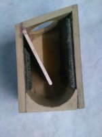
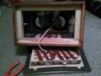
Rectangular boxes are easy to make, tapered boxes absorb the driver back wave; stick in an angled baffle and you get a taper in a box, and get a free brace. The dark stuff is carpet tile, in a vain attempt to absorb internal sound and dampen enclosure vibration, however I doubt it makes an lick of difference.
Attachments
^ This kind of structures create longer path lengths inside the enclosure than "empty box" has. Imagine "unfolding" the structure at the internal panel, you'd have very long enclosure.
Longer path makes standing waves even lower in frequency and hence less affected by (same) damping material and possibly worsens performance in this regard. But, allows you to tailor the standing waves as well, which might be taken advantage of, extend the low frequency response. Extending low frequency response might be useful for bass box, not so for a mid. Unless, the now longer standing wave is below the mids pass band making it less of an issue, and enables the standing waves within pass band absorbed more then it was a good thing. But it is kind of chasing ones own tail. Another possibility for such divider panel is to make a "stub", try and tune it to some existing resonance and kill it some as 1/4 wave resonator.
Structure like this is good sales argument for sure! 🙂 Otherwise I see it not too important feature in light of whole speaker system since it seems to pass problems around (shift from a frequencies to another). People use this kind of stuff with fullrange systems and less so with multiway systems even though on multiway systems this might work better than with fullranges since there is pass band and stop band for each way, possibility to push problems out of band and reap the advantages. Well, haven't utilized any so this is just theoretical thinking I'm writing about.
Rectangular boxes are ideal for DIY hobbyists since they are the easiest to fabricate. Keep them as small as possible to try and push any issues out of band, have them acoustically small to wavelengths they produce. This is not possible most of the time, but minimizes issues of rectangular boxes nevertheless. Other than that, more ideal shapes seem to exists.
If one thinks about it more, the compromises between outside and inside dimensions and how they are linked together, a no-closure becomes the most logical thing! And is even easier to build than a box since there is nothing to build! maybe some support structure to keep the transducers upright. Open baffle speaker. But, this is just from the perspective of enclosure. Now other things matter, like need for big drivers, complex crossovers and what have you, room positioning requirements.
Last edited:
^ That works for relatively short wavelengths only, you can have some tuned resonance in small form factor though. Problems remain for the lowest modes inside the box since they are bigger than the box, nothing that fits inside the box will not be very effective (as effective as to the shorter wavelengths, higher modes). Nevertheless the back wave energy needs to go somewhere and absorbed somehow or it just leaks out eventually so anything is better than none in this regard.
If you put more thought on it you can utilize the back wave to control the polar pattern outside the box by leaking it out intentionally and using the front radiation to destroy (destructive interference) the back radiation and vice versa! Compromise here is the low frequency extension, as one starts to leak the box (open baffle being the extreme leak) the low frequencies don't get supported by the box compliance and additional bass box might be required. This is good thing in my opinion, "audio quality" increase by having more cost and complexity. Some projects and people require to have low cost and low complexity, and then the compromise is to choose a system that supports the needs and a simple or complex box results even if it wasn't best option "audio quality" in mind. It is the whole system that matters, in the end.
If you put more thought on it you can utilize the back wave to control the polar pattern outside the box by leaking it out intentionally and using the front radiation to destroy (destructive interference) the back radiation and vice versa! Compromise here is the low frequency extension, as one starts to leak the box (open baffle being the extreme leak) the low frequencies don't get supported by the box compliance and additional bass box might be required. This is good thing in my opinion, "audio quality" increase by having more cost and complexity. Some projects and people require to have low cost and low complexity, and then the compromise is to choose a system that supports the needs and a simple or complex box results even if it wasn't best option "audio quality" in mind. It is the whole system that matters, in the end.
Last edited:

On paper, but hearing is believing. Understanding theory is one thing, testing with your own ears is another.But only at very high frequencies. It has been shown that the equivalent of 3-4” is necessary to reduce problems down into the midrange.
dave
One thing this simulation did show was that fluent shapes can be of importance even if their dimensions seem small at first.https://www.diyaudio.com/community/...ver-full-range-line-array.242171/post-6524791
There are some simulations performed in the link above and surrounding pages that show some of these effects. The addition of a 6mm chamfer in front of the driver had a positive effect, and the overall teardrop shape with significant rounding made for a very smooth response. Much can be worked out from basics, but the overall interaction of every component can be tricky to get right. BEM simulation or lots of prototyping is really needed if any sort of optimization is desired.
My own thought proces behind the shape was creating the most fluent shapes, from the cone out to the outer enclosure lines.
(partially hidden by the surround in my case due to driver choice)
Kind of like a horn turned inside out. 🙂
A quick opening up followed by taller smoother curves. Done to limit diffraction as much as possible.
For the inside wave just use dissimilar damping materials and check your impedance plots while filling the enclosure.
Leave some room for the driver to breathe.
(love the new drag and drop of the new website 🙂)
Maybe SIMULATIONS can be better, but
1: Hard to do at home, which was the topic of this thread
2: Actual audible difference. Go ahead, built and test. That is the fun of DIY, But for that cross=section you have above, I can pretty much assure you a 1/2 or 3/4 radius would sound no different.
Simulations are a guide. A hint. Very handy and I use quite a few, but I also use 45 years of experience and my wife's outstanding hearing.
Another hint: Folks get so hung up with cabinet back-waves when the basket is 10 times worse. A poster child is the FE85 and similar small drivers. One should always look at the entire system, not over-focus on one thing they heard about on a forum. Bottom line: test.
I have to wonder if you looked at the outputs from the simulations and CAD drawings as I find it highly unlikely that these two directivity graphs will sound the same.Maybe SIMULATIONS can be better, but
1: Hard to do at home, which was the topic of this thread
2: Actual audible difference. Go ahead, built and test. That is the fun of DIY, But for that cross=section you have above, I can pretty much assure you a 1/2 or 3/4 radius would sound no different.
When looking at directivity, BEM sims are very accurate, there is a reason why all the major manufacturers use BEM and FEM simulations. There is always a need to build and verify but they are much more useful than your comments suggest.Simulations are a guide. A hint.
- Home
- Loudspeakers
- Multi-Way
- Ideal speaker shape to make at home