You are missing my point. Graph are nice. But use your ears in a real room. They get you close quicker and can sometimes point out something you did not notice. Invaluable, but just one more tool. Prototype to a CAD, but then measure and tune with your ears. Nice to go back and see what the simulation says about your final design. You can often learn the best target is not intuitive. This is called "experience"
You are also missing the point of diminishing returns in a "EASY TO BUILD DIY" as the OP is asking, not the theoretical perfect cost no object if you have full size CNC capability. A lot of directivity issues get quickly swamped by the room. Unfortunately a subject often lost on most DIYers and even more unfortunately, impossible to guess for an OEM. Are you assuming there is no reflection within 2 feet of the speaker? Are you assuming the listener is roaming around the room at different heights? Or is the listener sitting in their favorite chair? Maybe it is my, but my speakers are in my living room, not on a pole in an anechoic chamber.
I learned long ago, after a simple offset driver box with moderate radius, there are far more important things to spend your time and money on. The crossover and drivers come to mind. A lot of those fancy graphs go out the window when you add a second driver and a crossover.
Many many bright engineers get obsessed with one parameter. Klipsch and Bose to name two, and fail to look at the overall system. Their physics were good. Their designs met their narrow pet parameter goal, but the result was horrible. On the flip side is a speaker like the new KEF LS50. It has a sweet spot around of inches. Just tilt your head and the image leaps across the room. Great nearfield monitor, horrible in a living room. They seem to not have paid enough attention to the simulations as you are showing. Not only the issues of phase coherence in a coaxial drive, but it is harder to deal with diffraction and reflection within the cone.
Tell us how you really feel 🙂.
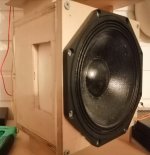
For the record, my complex shape box was build using hand tools in my garage, no fancy CNC.
Easy to build? Debatable. Does it work? Yes it does, verified with my ears 😉.
(after simulating and measuring my way there)
For the record, my complex shape box was build using hand tools in my garage, no fancy CNC.
Easy to build? Debatable. Does it work? Yes it does, verified with my ears 😉.
(after simulating and measuring my way there)
Last edited:
I have not heard your speakers so that would be total bull dropping's conjecture to suggest they have any fault. Just suggesting the difference between a very complex shape because CAD says so and a simple radius it quite small when put into a real room and easily overshadowed by room, driver, and crossover issues. I have found the bandwidth where the drivers are reasonably in phase to be more significant than some suggest. There are some outstanding speakers with simple box shapes and less round over than even I manage. How can that be? Because they look at more of the overall issues. The more exotic the shape, the further away from each other the mid and tweet wind up, and so the bigger the problems with off axis. I prefer to trim my flange and basket to shift those problems as high as I can and concentrate on the bandwidth were the drivers are reasonably in phase.
One could have more fun. Make it round-ish and go to town with a rasp or angle grinder making some ugly convoluted random shape to further distribute any refractions and confuse baffle step. Maybe dimple the baffle with varying size, randomly placed dents. Not easy, hard to simulate, and most likely to fail WAF. Actually, with the computing power available, I am surprised no OEM has done this and then printed or machined the result. Design is far cheaper than manufacturing.
Everything we can measure we can't hear. Everything we hear we do not always know how to measure. No two rooms are identical and no two ears ( even on the same head) are identical. FWIW, even some measure neglectable difference, the felt doughnuts on my tweeters are clearly audible. They were easy to make needing only a pair of scissors.
You'll find out the bevels / roundovers need to start right at the driver edge to be most effective since effective bewel / roundover size is related to wavelengths, which relate to the issues, baffle size and transducer size.
Yes! I use to 'harp' on this way back when to apparently mostly 'deaf ears', so finally gave up, though IIRC a few folks did try it, but can't remember if they carried it as far as my preferred 'extreme' of shallow/wide MLTL terminating in an Onken inspired row of vents on the sides ~after the Jensen Ultraflex corner horn, i.e. basically portable in-wall speakers when near/at a room boundary.
It makes sense that larger bevels work at lower frequencies. But is also true that sharper edges diffract more at higher frequencies. So my question is, does that 45 degree bevel work any better than a 90 degree edge at 4KHz?
Yes. It works at all frequencies above the LF cutoff of the bevel.
dave
What you have illustrated is a half-wave TL, i believe this was something i mentioned earlier. For midrange use i like to make them quarter-wave and damped till aperiodic.
BTW: the rounded bit at the bottom is counter-productive.
dave
Last edited:
CrackedCase showed a parallel (to the baffle) “holey-brace”.
I use a simialr technique to distribute (many) of the boxes standing-wave structures.
Here is an extreme example. Holes do not line up, so in conjunction with the tapered sides, creates a cinsiderable number of different path widths.

Note that the braces have been cut such that none of them are right behind the driver to cause early reflections.
dave
I use a simialr technique to distribute (many) of the boxes standing-wave structures.
Here is an extreme example. Holes do not line up, so in conjunction with the tapered sides, creates a cinsiderable number of different path widths.
Note that the braces have been cut such that none of them are right behind the driver to cause early reflections.
dave
'Distributed" is good. But does all that work really overshadow other issues? Does make the box a lot bigger!
Not a lot more volume. And with the miniOnken alignment the box is small already. And beeds few double thickness panels, elegance over brute-force. It does not move at any frequency the TAD 1601A is used at.
dave
dave
The bracing seems more like brute force to me 🙂 I'm not sure if that does anything else than creates even longer path lenghts than between any two walls, if is "visible" at all. The thing is, lowest mode is half wavelenght of any dimension of the box. This is so large there is no structure that fits inside the box that would obstuct or break it down, or scattet it, what ever. And for the higher ones typical acoustiv damping materials work just fine. Bracing is to add stiffness to the walls and for that it surely does work. Damping material and CLD damping on the walls /bracing makes more sense. But, what ever works of course, havent built either yet.
I think the onken alignment does the most work if the box doesn't show modes in the impedance plot. Never saw measurements of such thing though, but I believe it could prevent standing waves to form, as the long ports could work as pressure leak right at the corners and all the height. Might even provide somekind of pattern control? Or just make things lumpy by leaking the backwave unevenly making weird response. But it is just my speculation until measurements show how it works out.
I think the onken alignment does the most work if the box doesn't show modes in the impedance plot. Never saw measurements of such thing though, but I believe it could prevent standing waves to form, as the long ports could work as pressure leak right at the corners and all the height. Might even provide somekind of pattern control? Or just make things lumpy by leaking the backwave unevenly making weird response. But it is just my speculation until measurements show how it works out.
LF will not see the braces. higher frequencies will as well. Low density damping can be placed over all the holes to further reduce HF waves.
Brute force would be making it of triple thick 18mm plywood with no bracing. And i don’t think it would be as good.
dave
Brute force would be making it of triple thick 18mm plywood with no bracing. And i don’t think it would be as good.
dave
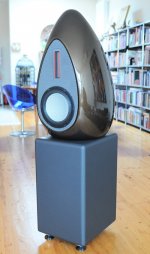
Except for the flat baffle. Mach 5 did the eff 2-way midTweeter egg better, and B&W probably represents th eleading edge.
dave
dave

Here is best I've ever come up with. No bottom end, but least diffraction and resonances of my builds, passive cardioid. Cheapest smallest and fastest build, no need for recess or bracing 😀 doesn't get any better for home builder, but it is some work to tune the response and requires woofer and tweeter at least to make a system, with compatible requirements for those as well. Bass boxes are easy to build, just plan the problems outside of the pass band. tweeter waveguide doesnt need box at all which makes overall easy build without much structure related problems. Certainly less than all 3 drivers on rectangular single box without roundovers. But possibly demands for active xo so.. pick where the easy part is, in the garage or with a credit card or on a design desk.
Ideal structure depends on the application and design of course. Ideal shape for home is simple box since minimal tools required and cost is low. Or just get the thing printed somewhere and call it a day.
Ideal structure depends on the application and design of course. Ideal shape for home is simple box since minimal tools required and cost is low. Or just get the thing printed somewhere and call it a day.
Attachments
Last edited:

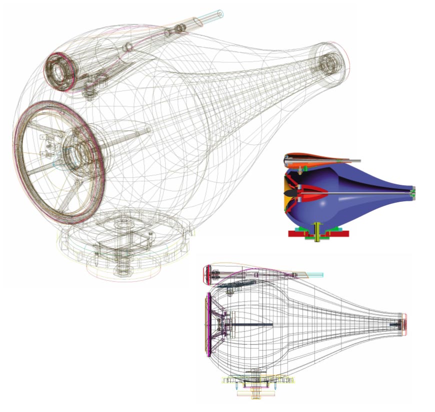
It's a closed box, it's just a taper ( like B & W nautilus ) bent around to fit in a box. They're VERY small, about 80 mm tall - a computer speaker that needs a sub.
What you have illustrated is a half-wave TL, i believe this was something i mentioned earlier. For midrange use i like to make them quarter-wave and damped till aperiodic.
BTW: the rounded bit at the bottom is counter-productive.
dave
- Home
- Loudspeakers
- Multi-Way
- Ideal speaker shape to make at home