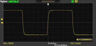
I got my parts in today and put 12pF in parallel with the 100k feedback resistor. Circuit looks pretty stable and 10kHz square wave looks pretty good now. I'm tied up for the next couple of weeks going out of town but I should be able to do some distortion measurements pretty soon at higher levels than before.
Attachments
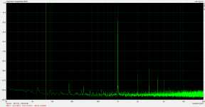
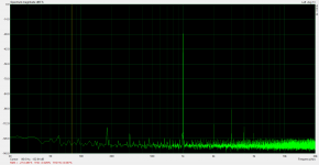
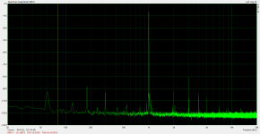
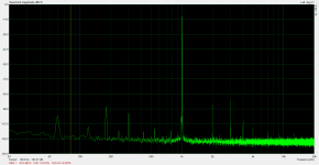
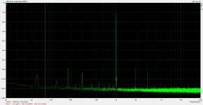
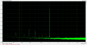
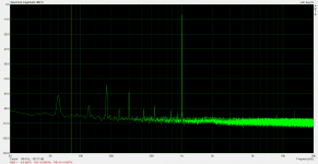
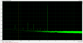
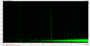
Well, I did get some test time before the trip. Conditions were 1080V B+, 600V plate idle voltage, 35V screen. Here are the results:
10Vrms, .012% THD (buried in noise)
20Vrms, .0063%
30Vrms, .0087%
50Vrms, .0074%
100Vrms, .0099%
160Vrms, .014%
200Vrms, .018%
250Vrms, .029%
300Vrms, .047%
323Vrms, .061%
I expected an increase in distortion since I raised gain to 13.3 (from 10) but a reduction due to the decrease in screen voltage. Looks like the screen voltage reduction had the stronger effect.
In all, I think these are astounding results. At 160Vrms output (the requirement to drive my Unity-Coupled amp to clipping) this approach results in distortion that is two orders of magnitude lower than any triode I have tested at similar output levels.
Attachments
-
 300VrmsB.png79 KB · Views: 95
 -
 250VrmsB.png79.9 KB · Views: 89
 -
 200VrmsB.png79.8 KB · Views: 101
 -
 160VrmsB.png80.9 KB · Views: 97
 -
 100VrmsB.png80.2 KB · Views: 104
 -
 50VrmsB.png79.6 KB · Views: 208
 -
 30VrmsB.png80 KB · Views: 203
 -
 20VrmsB.png81.6 KB · Views: 224
 -
 10VrmsB.png81.3 KB · Views: 241
 -
 323VrmsB.png84.8 KB · Views: 108
Hey SpreadSpectrum,
I've been following this project with interest because I'd like to try a cathode follower output for a low power amp (2-3W). I'm looking for about 350V ptp or 120Vrms. I know you've been playing mostly with CCS loads, but did you experiment with choke loads at any point? I'm trying to keep my amp down to a single B+ (and cathode biased).
I've been following this project with interest because I'd like to try a cathode follower output for a low power amp (2-3W). I'm looking for about 350V ptp or 120Vrms. I know you've been playing mostly with CCS loads, but did you experiment with choke loads at any point? I'm trying to keep my amp down to a single B+ (and cathode biased).
Hey SpreadSpectrum,
I've been following this project with interest because I'd like to try a cathode follower output for a low power amp (2-3W). I'm looking for about 350V ptp or 120Vrms. I know you've been playing mostly with CCS loads, but did you experiment with choke loads at any point? I'm trying to keep my amp down to a single B+ (and cathode biased).
I didn't try a choke load. The thing that led me down the road with the CCS load is that a mosfet CCS has a isolated low impedance output built in at the source of the mosfet, so it is perfect for driving the feedback resistor without letting the pentode see the load.
If you were to use a choke, you would either have to drive the feedback resistor from the plate of the pentode or you would have to use a buffer like a mosfet follower (like I did at first). The problem with using a buffer is that it would have to have a positive rail that is twice the B+ for the choke. If you had such a rail, you might as well use a CCS at that point and get much better LF performance.
Now if you had a good quality plate choke, it might be worthwhile to see how good performance could be with higher-value feedback resistances. It would make noise go up, but I haven't explored at what value that starts becoming a real problem in a real amp design. It may be perfectly okay to raise the resistances to a point where loading on the pentode plate isn't a big deal. Performance may still be pretty good with the 100k feedback resistor and a choke load.
I just haven't explored any of this even with sims or back-of-envelope calculations.
- Status
- Not open for further replies.