I got the ringing mostly tamed playing with different gate stoppers and did some distortion measurements today.
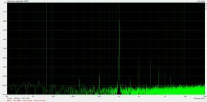
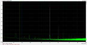
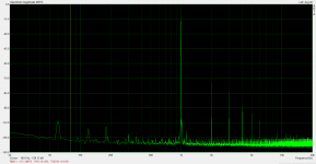
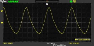
I tested up to 276Vrms output (spectrum attached). This is getting to the ballpark of being able to drive CF output stages. I can go up further from here without hitting the supply rail but high order harmonics rise rapidly above this level.
This is with ~980V on the B+ and plate idling at ~550V, so I am getting up to within ~40V or so of the positive rail. There is no reason I can't run this with a higher supply voltage. With the power transformer I have, I should be able to do some tweaking and get ~1150V.
If I can eventually get up to ~320Vrms output with this low distortion I'll be happy. Almost there...
Attachments

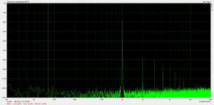
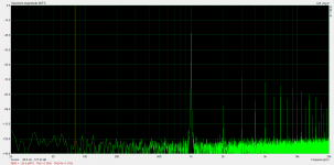
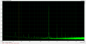
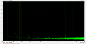
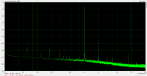
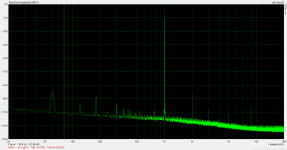
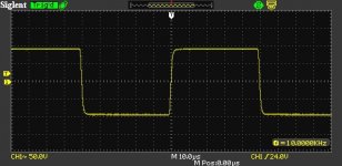
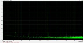
I increased B+ and did some more testing. I got up to 300Vrms with .24% THD after which I got a rapid rise of lots of high-order distortion.
Then I switched to a higher tap on my power transformer and bumped B+ up another 35V or so and I got the same result, onset of clipping at just above 300Vrms.
Then it occurred to me that the ADA4700 was the one doing the clipping, I switched to the ADA4700 output and confirmed that it was clipping at that level. So it looks like a can't test to 320Vrms like I wanted to without building a higher voltage driver and I'm not going to do that just to get that last little bit. I'm calling this acceptable. It should work with a driver that can swing enough and adequate B+.
I think I'll order a pair of SE transformers and build a bench amp and see how it goes.
I have attached results at 285Vrms, 300Vrms, and 305Vrms
Attachments
Playing around with ideas and remembered an article by Nelson Pass that supports this concept http://www.diyaudio.com/forums/tubes-valves/288372-idea-driver-cf-output-stage-2.html#post4682096. Posting just for reference. Take a look at the front end. His does not have a cascade device, but that should matter very little.
http://www.diyaudio.com/forums/diyaudio-com-articles/154777-burning-amplifier-ba-1-a.html
http://www.diyaudio.com/forums/diyaudio-com-articles/154777-burning-amplifier-ba-1-a.html
Last edited:
Some time ago I attempted to eliminate the follower that drives the feedback network and drive the feedback network from the CCS "mu" output (the source of the bottom fet). This resulted in a CCS that would no longer function properly. This was with the board with 1500V+ (expensive) parts on it, so I decided to go back to the lower voltage board and experiment some more on the simpler circuit. This time I included protection zeners on the CCS fets (I have omitted them in the past since they seemed to be fine without them).
I ran some tests under similar conditions to earlier tests (in post 35) to see what kind of difference there was with the simpler circuit. Results were as follows:
.014% @ 10Vrms
.023% @ 20Vrms
.028% @ 30Vrms
.044% @ 50Vrms
.075% @ 75Vrms
.12% @ 100Vrms
Results were very similar for all but the smallest levels. There was a bit more second harmonic at lower levels. I consider the simpler circuit to be an overall improvement due to the simplicity factor and the fact that the output is now taken from a point that has more standing current (the current of the feedback network as well as the EL34 itself) so has increased capability to drive downstream capacitance.
Next test is to build up a high-voltage version with protection diodes and see if it works.
Attachments
Playing around with ideas and remembered an article by Nelson Pass that supports this concept http://www.diyaudio.com/forums/tubes-valves/288372-idea-driver-cf-output-stage-2.html#post4682096. Posting just for reference. Take a look at the front end. His does not have a cascade device, but that should matter very little.
http://www.diyaudio.com/forums/diyaudio-com-articles/154777-burning-amplifier-ba-1-a.html
Thanks, I'll check it out.
I ran an extra series of tests on the circuit on the post above to show what performance would be if you optimized the operating point a bit for the amplifier we were talking about via PM.
Here is what distortion would look like if you raise the plate idle voltage to 330V or so. That would still give you plenty of output voltage to drive the output stage to clipping. You could use the same supplies for the driver and the output stage. Measurements are for 10, 20, 30, and 63Vrms output.
Of course, you could also use an EL84 with the plate at ~300V and distortion would only be a little bit higher.
Attachments


I set out experiment today to answer some lingering questions I have had about this circuit. One thing that I have noticed is that distortion is higher at low plate voltages. This makes sense if you look at EL34 (or other tube) characteristics. Curves tend to have variable (and sometimes negative) slope there. So what can be done?
It appears, from looking at characteristics at various screen voltages, that the kinky curves mellow out at lower screen voltages. So was the 100V too high that I was using?
For distortion testing today, I decided to keep plate idle voltage at 200V and vary the screen voltage. Then I would measure RMS voltage output at 0.1%, 0.2%, and 0.3% THD and just see what happens. I did this for EL34 (Electroharmonix), 6L6GC (Winged C), and KT66 (Sovtek). Results are below.
- EL34 -
V Screen | Vout 0.1% | Vout 0.2% | Vout 0.3%
100V 48.7Vrms 72.8Vrms 93.4Vrms
075V 49.1Vrms 77.7Vrms 102.5Vrms
050V 53.0Vrms 87.0Vrms 105.3Vrms
040V 61.0Vrms 92.0Vrms 110.4Vrms
035V 66.0Vrms 98.0Vrms 112.5Vrms
030V 68.0Vrms 93.0Vrms 107.0Vrms
025V 18.0Vrms
- 6L6GC -
V Screen | Vout 0.1% | Vout 0.2% | Vout 0.3%
100V 32.0Vrms 52.6Vrms 68.9Vrms
075V 39.6Vrms 61.8Vrms 83.5Vrms
050V 45.0Vrms 75.0Vrms 99.3Vrms
045V 47.2Vrms 74.9Vrms 102.0Vrms
040V 50.0Vrms 79.6Vrms 105.8Vrms
035V 47.7Vrms 73.3Vrms 90.8Vrms
- KT66 -
V Screen | Vout 0.1% | Vout 0.2% | Vout 0.3%
060V 38.2Vrms 65.0Vrms 87.2Vrms
050V 37.4Vrms 64.7Vrms 90.3Vrms
040V 41.7Vrms 69.9Vrms 97.3Vrms
035V 43.7Vrms 66.9Vrms 84.0Vrms
6L6 and KT66 had generally worse performance than EL34 and had peak performance at 40V screen rather than the peak performance the EL34 had at 35V on the screen.
I'm quite happy that EL34 ended up being the best performer since they are about the cheapest new production tube that can handle high plate idle voltages, which is crucial in developing a driver for CF output stages.
This was a good learning experience. Next I will be building another CCS board for testing at 1000V B+. I damaged the previous board I was testing with.
Edit: It looks like the forum software deletes all of the extra white space characters that make the columns line up in the tables. Nice.
Last edited:
Is this a possibility using a Cascaded Jfet follower on the input, with feedback going into cascade device (like smoking amp's drawing)?
I've spent some time looking at this and I'm not sure how it works.
In another thread, I asserted that lower Vg2 makes more voltage gain. Up to a point where you can't pull the load.
V Screen | Vout 0.1%
100V ----- 48.7Vrms
075V ----- 49.1Vrms
050V ----- 53.0Vrms
040V ----- 61.0Vrms
035V ----- 66.0Vrms
030V ----- 68.0Vrms
025V ----- 18.0Vrms
This is a feedback circuit. Higher raw gain translates to lower distortion. Dropping Vg2 from 100V to 30V increases gain around 1.4 times, thus lower THD, or higher output at the same THD.
Until you get to 25V, which apparently the tube can't pull this specific load with that low a Vg2.
> It looks like the forum software deletes all of the extra white space characters
No, they are there. ("View Source"). Many browsers obey the HTML philosophy of not taking repeated white-space literally.
Dashes or underlines are a 2-thumb typist's easy hack.
The forum formatting surely has Tables, but forum-code tables are even more tedious than raw HTML tables and I never touch the stuff.
{CODE} will sometimes respect whitespace. (Again, may depend on the broswer.)
Attachments
This is a feedback circuit. Higher raw gain translates to lower distortion. Dropping Vg2 from 100V to 30V increases gain around 1.4 times, thus lower THD, or higher output at the same THD.
What I am seeing is a reduction in distortion of 3x at small voltage swings (10Vrms) to 2x at large swings (100Vrms).
So it seems to point to either a larger increase in gain than 1.4x or a combination of increased gain and less bad curve behavior at low plate voltages (which is what I think is going on).
Until you get to 25V, which apparently the tube can't pull this specific load with that low a Vg2.
I think at 25V the feedback network would need to drive the control grid positive to maintain stage gain but it doesn't have a low enough Zout to accomplish this. The Vg=0 line is encroaching on our load line.
Last edited:
> I think at 25V the feedback network would need to drive the control grid positive
Yeah.
As this is usually awkward (extreme loading on your 10K input resistor), we don't usually try to go there.
It could also be predicted from the EL34's max current at high Vg2 (300mA?), the current you run at (10mA?), the Vg2 ratio, and Child's law. (1/10)^(3/2) is about 1/30, so 300mA at high Vg2 may be 10mA at 30Vg2, and any lower it starves-out.
Child's Law is never exactly ^3/2 for real tubes, and 10:1 range of current is a lot of change, so the estimate is not exact, but not far wrong.
...the estimate is not exact, but not far wrong.
Hey I love it when the formulas and the real world match up!
This has been a real interesting experiment for me as I will eventually have to come up with a solution to replace the 841s (too hard to get them) in my homebrew Unity-Coupled amp. Already, this is performing orders of magnitude better and there are no problems sourcing EL34s. I do feel a bit like I am wasting the power potential of an EL34 on 10mA but there are just not many other candidate tubes for high idle plate voltages that perform this well. Of course, this could be done with great success with an EL84 if 300V plate idle voltage is sufficient.
Now I want to go build a bunch of amplifiers now that I have a driver with such low distortion.
I've got a set of SE output transformers coming and I'm going to see if I can rig up an amp on the bench to have this circuit drive a follower output stage. I don't think SE is the way to go for top performance but I figured I'd build at least one SE amp before I'm through with tubes.
> with an EL84 if 300V plate idle voltage
At 10mA, I would not worry about ANY modern EL84 at 400V even 440V on plate. I think the original rating was conservative (why would you need more?) or left room for Marketing (sell non-junk EL84 as 7189 for more money). A lot of commercial amps (more in the guitar world) abused EL84 ratings, also people buy EL84 for 7189 sockets, and the modern makers allow for such abuse.
A hot 7189 amp would burn-up a low-spec EL84 (heat plus voltage is worse than either alone), but you are far from hot. 400V 10mA is 1/3rd of rating.
400V on plate suggests 800V available supply. More than I like in the home.
Well, I would certainly welcome using EL84 for the Unity-Coupled amp driver stage rather than the EL34. Just seems like a real waste to run an EL34 at 4-5W. The heater takes more power than that.
As far as 800V+ supplies go, I think this SE amp that I am making will be the only one of those that I do. I know how to take precautions for it but it does make me more nervous.
Luckily, for the UC amp I can just tie the driver CCS supply to the opposite power tube plate. I plan on running driver at 400V idle and the power tube supply is 450V, so the CCS will always have 50V across it. No need to have a separate extra high voltage supply.
Hi SpreadSpectrum,
many thanks for posting these results - I am working on PP pentode driver at the moment and will try the impact of lower G2 on the distortion!
Cheers, Erik
many thanks for posting these results - I am working on PP pentode driver at the moment and will try the impact of lower G2 on the distortion!
Cheers, Erik
Hi SpreadSpectrum,
many thanks for posting these results - I am working on PP pentode driver at the moment and will try the impact of lower G2 on the distortion!
Cheers, Erik
Thanks, Erik. I was surprised that it took me so long to realize that it might help.
The plot thickens...
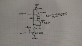
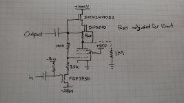
So here is a current schematic of what I am working with at the moment. I increased the gain by decreasing the source resistor for the p-channel fet. I also put an IXYS part on the top of the CCS cascode to handle the higher B+.
I was totally excited to power everything up and prove that it could drive a CF output stage with low distortion and I got oscillations. 🙁
Fortunately I stumbled onto a fix. I started measuring voltages with the multimeter and found that simply connecting the multimeter from ground to the EL34 plate stopped the oscillations. Apparently 1M is enough to do it. I would prefer not to degrade CCS performance by loading the plate directly at audio frequencies so maybe a series RC will do it that only comes into play at ultrasonic frequencies. More experiments to follow. I probably don't have any suitable capacitors so I'll probably have to make an order.
Edit: forgot to add that I am using 500R stoppers on both CCS fets.
Attachments
Last edited:
- Status
- Not open for further replies.
- Home
- Amplifiers
- Tubes / Valves
- Idea for driver for CF output stage