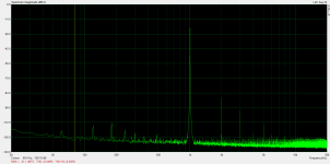
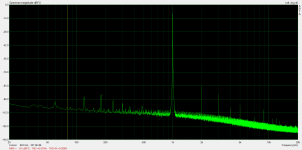
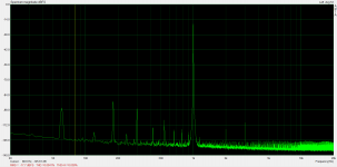
Well, I think I have a good signal generator amplifier for further experiment on this circuit idea. I added some filtering to the ADA4700 to limit bandwidth and suppress distortion a bit.
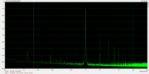
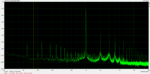
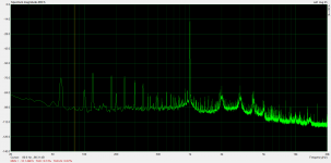
Attached is the distortion spectrum. Anything above 3rd harmonic is unmeasurable and distortion is <.01% all of the way up to the +-48V rails. This should be adequate for generating drive voltages to drive the EL34 all of the way up to where I want to test.
Next step is to construct the higher voltage B+ for further experiments with the EL34.
Note: the ~8.7k peak is some artifact of my measurement setup and is always present even without signal.
thanks for posting your findings on the ADA4700. COuld you tell a bit more about the applied filtering, employed PS, layout?
Many thanks, Erik
thanks for posting your findings on the ADA4700. COuld you tell a bit more about the applied filtering, employed PS, layout?
Many thanks, Erik
For filtering, I simply put an 820pF capacitor in parallel with the 100k feedback resistor to give a cutoff frequency of 2kHz. I could probably do a bit better on harmonic suppression with a bit more capacitance but I'd have to be prepared to drive it a bit harder as it would start affecting the amplitude of the fundamental more if I did that.
For the supplies, I used two cheap 48V medical wall-wart types with isolated outputs and stacked them. They were made by Meanwell. I didn't even use local bypass caps near the op-amp, which would definitely be good practice, but noise floor seems very low as-is.
As far as layout goes, you can see that in post #19. The only thing that has changed since the picture is that I hung a capacitor from the resistor on the right. As you can see, layout is not particularly tight. I had to bend leads and flip the chip so that I could put an improvised heatsink made of a couple of wires on the pad. It seems adequate. The op-amp has a thermal shutdown feature and I haven't seen it engage, but then again I haven't left it running at full amplitude for long periods of time. The only thing that has changed since the picture is that I hung a capacitor from the resistor on the right.
I am at work and am leaving on an out of town trip for the weekend right after work today, but I can get you part numbers for power supplies and a schematic for the ADA4700 section as implemented when I get back next week.

Thanks for the info SpreadSpectrum!
I will include on the these chips in my next order,
cheers, Erik
I will include on the these chips in my next order,
cheers, Erik
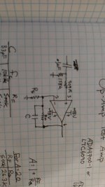
Well, it's the tube section here.It gets upset with all those mosfet's and ic's ! 😱Here is a schematic of the ADA4700 test preamp:
Rf is 100k, C is 820pF, and Rg is 5.23k
Edit: not sure why the image rotation is off. It is fine on my computer. 🙁
What if you try doiing it with tubes ?

Mona
Attachments
Well, it's the tube section here.It gets upset with all those mosfet's and ic's ! 😱
What if you try doiing it with tubes ?
Mona
I should have known that the op amp would upset the board software. 😀
I was just using the ADA4700 to make a low distortion amplifier to test the CCS-loaded pentode circuit to higher levels. I wanted it to be simple and easy.
I'm using the Mosfets in the EL34 circuit just really to see how low distortion can be on an EL34 with CCS load and so-called "Schade feedback." Most of the Mosfets can be replaced with tube followers if one desires, except the p-channel fet.
Does this ADA4700 outperform a mosfet concertina with 3 ma @ 200v B+ 2 * 15k resistors
Well, you would need two ADA4700s to make a phase splitter, but I thought the performance as a simple amplifier was very good. I don't know if someone has some distortion measurements available online of a mosfet concertina under those conditions. It would be interesting to compare.
The thought of using the ADA4700 as an input stage for a tube amp has crossed my mind. I'd probably use two of them and configure them like the first stage of an instrumentation amp.
the ADA4700 certainly provides lots of swing plus sufficient current to drive a KT88 or other large tube into class A1 conduction.
I have been doing the reverse of this where tube drives silicon and tube of choice is 6922 twin triode. over 2A of current can be obtained with a BJT fed off the anode.
I have been doing the reverse of this where tube drives silicon and tube of choice is 6922 twin triode. over 2A of current can be obtained with a BJT fed off the anode.
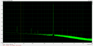
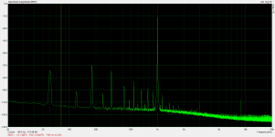
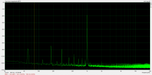
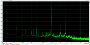
After testing bandwidth, I hooked the ADA4700 up to the EL84 to do some higher output distortion tests.
Results:
.0084% @ 10.7Vrms
.019% @ 21.6Vrms
.027% @ 30.6Vrms
.049% @ 50.7Vrms
.060% @ 75.4Vrms
.083% @ 101.1Vrms
I'm very pleased with these results.
Results:
.0084% @ 10.7Vrms
.019% @ 21.6Vrms
.027% @ 30.6Vrms
.049% @ 50.7Vrms
.060% @ 75.4Vrms
.083% @ 101.1Vrms
I'm very pleased with these results.
Attachments


I just realized that I never tested the bandwidth of the cheap $40 signal generator I was testing with. It is 3dB down at 800kHz, and it is down a bit at 400kHz.
So I'll call the EL84 400kHz+. I measured the EL34 afterward and it was 3dB down at 300kHz, so a little less bandwidth as built here in my test circuit when I plug in the bigger tube.
So I'll call the EL84 400kHz+. I measured the EL34 afterward and it was 3dB down at 300kHz, so a little less bandwidth as built here in my test circuit when I plug in the bigger tube.
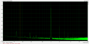
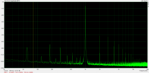
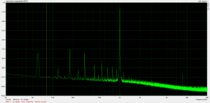
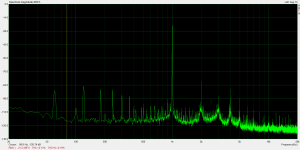
I did another round of testing similar to what I did for the EL84 on the EL34. What I did was set the idle plate voltage to give minimum distortion at 100Vrms output. Then I measured distortion at that and lower levels. Here are the results:
.0071% @ 10.0Vrms
.0098% @ 20.2Vrms
.023% @ 30.2Vrms
.050% @ 50.1Vrms
.090% @ 75.7Vrms
.16% @ 101.6Vrms
.0071% @ 10.0Vrms
.0098% @ 20.2Vrms
.023% @ 30.2Vrms
.050% @ 50.1Vrms
.090% @ 75.7Vrms
.16% @ 101.6Vrms
Attachments


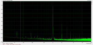
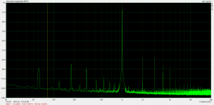
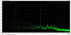
After that test I decided to tweak settings to see what would affect distortion. First I started by varying screen voltage. I saw pretty much no change in distortion from 80V to 150V on the screen (and changing bias to keep plate idle voltage the same). That surprised me. I figured that varying screen voltage would make a difference. I prefer to keep screen voltage somewhat low since that reduces the necessary negative bias on the gate of the p-channel fet.
After I did that, I varied idle plate voltage with a 30Vrms output signal to see where in the plate voltage range was most linear. It turned out that setting the plate voltage as high as possible without clipping minimized distortion. I have attached a distortion measurement at 350V idle plate voltage and 30Vrms output. .0092% distortion with a nice waterfall harmonic characteristic. I can't wait to see what happens when I construct a supply that is capable of swinging large output voltages from that and higher operating points.
I now have all of the parts that I need to construct the 800-1000V variable supply to test the EL34 to voltage outputs that should be capable of driving a CF output stage, so those test results should be coming soon.
I hope I'm not counting my chicken before it hatches but this circuit may also end up as a substantial upgrade to the 841 driver in my Unity-Coupled amp.
Edit: Keep in mind that my driver amp is putting out ~.009% distortion, so I really have no ability to really measure the distortion of the EL34 here at this operating point. It appears to be very low, whatever it is.
Attachments

Last edited:
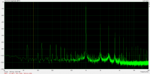
I finished the HV power supply and set it up for 800V (I am waiting to go for the full 1000V because I currently have 900V upper FETs in the board). I set the EL34 plate idle voltage at 450V.
I got what I consider to be astoundingly low distortion for these voltage swing levels.
.0027% @ 10Vrms
.0014% @ 20Vrms
.0072% @ 30Vrms
.0047% @ 50Vrms
.0041% @ 75Vrms
.0057% @ 101Vrms
.041% @ 200Vrms
.090% @ 230Vrms
I will attempt 300Vrms when I get the 1500V CCS/FET driver board built up with 1000V B+.
Attachments


One thing I am seeing is that I get a lot more distortion if part of the waveform has the plate voltage dip below 100V or so. This makes sense, since the EL34 plate curves don't settle down to nice flat, straight lines until they go above that region. If I keep things above that region I can get really low distortion even at very large voltage swings.
I took some measurements from the 841 stage in my Unity Coupled amplifier for comparison.
.13% @ 10Vrms
.072% @ 20Vrms
.17% @ 30Vrms
.13% @ 50Vrms
.24% @ 75Vrms
.42% @ 101Vrms
1.84% @ 200Vrms
These aren't exactly apples to apples since I measured this in-circuit and on the EL34 test setup they are being driven by a cleaner source and have a lighter load.
.13% @ 10Vrms
.072% @ 20Vrms
.17% @ 30Vrms
.13% @ 50Vrms
.24% @ 75Vrms
.42% @ 101Vrms
1.84% @ 200Vrms
These aren't exactly apples to apples since I measured this in-circuit and on the EL34 test setup they are being driven by a cleaner source and have a lighter load.
Attachments

For the CCS I ended up using an IXTH2N170D2 (replaces 10M90S) as the upper device in the cascode and I used an STW4N150 (replaces FQP2N90) for the follower for the plate feedback. This gets me from 900V max rating to 1500V (1700 for the CCS).
I just did some bandwidth testing just now with the new parts and the circuit was 3dB down at 375kHz.
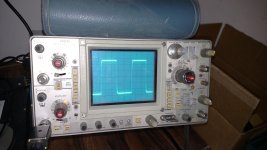
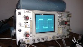
I have attached an image of a 20kHz square wave and as you can see there is ringing this time with the new parts where there was none before. The frequency of the ringing is ~1.1MHz. I'll have to order some parts to try to tame it.
I just did some bandwidth testing just now with the new parts and the circuit was 3dB down at 375kHz.
I have attached an image of a 20kHz square wave and as you can see there is ringing this time with the new parts where there was none before. The frequency of the ringing is ~1.1MHz. I'll have to order some parts to try to tame it.
Attachments
- Status
- Not open for further replies.
- Home
- Amplifiers
- Tubes / Valves
- Idea for driver for CF output stage