So I thought I would try my hand at simulating this circuit using LTSpice.
I created the attached schematic, but it won't run because it gives me the error;
Unknown subcircuit call in:
xu1 n003 p001 n009 nhsv6as7 a g k
I am new to this program, and don't want to waste inordinate amounts of time arsing around with it so any pointer would be nice.
Shoog
I created the attached schematic, but it won't run because it gives me the error;
Unknown subcircuit call in:
xu1 n003 p001 n009 nhsv6as7 a g k
I am new to this program, and don't want to waste inordinate amounts of time arsing around with it so any pointer would be nice.
Shoog
Attachments
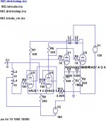
Check that you really have the "nhsv6as7" in any of your specified *.inc´s. They should also read like in this example:
.inc dmtriodep.inc
etc. etc.
.inc dmtriodep.inc
etc. etc.
Last edited:
The instructions I had said put a . between the inc and the triode.inc.
I will try it without.
Shoog
I will try it without.
Shoog
My apologies for re-opening an old thread - however - your design, panos29, is the one that serves my purposes best. Have you updated this design? Would you mind posting the power supply schematic as well? Many thanks in advance!!I used the following schematic with excellent results, very dynamic with good and fast slam and very analytical mid and highs, power was around 6 watts limited by driver swing. On my horn poaded Tannoys 6 w were more than enough.
Hello -
I am following this thread with great interest. Did anything come of this design with the 5687 front end? What are the voltage needs going into the 5687 tubes? I am attempting to adapt this design into a mono PA/Bass guitar amp.
Also - could you help me located the torroid you are using for the driver section? Is it an Antek? Their web site is very hard to use - can you please provide specifics so I can obtain a quote from them?
I don't mean to hijack this discussion - just hoping for more. thx.
The version with the 5687 was built and works well. The +B on the front end needs to be about 150-170V.
For the interstage I used something like this;
MULTICOMP|MCTA050/55|TRANSFORMER, 50VA, 2 X 55V | Farnell Ireland
Any brand of similar spec should do.
What are you going to apply to the front end for adequate gain?
The power supply is very much dependent on what power transformer you can lay your hands on. 170V front end and 130V output is a very unusual voltage to design around, and I built the circuit to utilize a huge PA transformer I had lying around. You could try using isolation transformers - or stacking secondaries of smaller transformers. It is not practical to suggest a power supply without knowing the transformer you will be using. Then any power supply can be designed successfully using PSUII
Shoog
Last edited:
Shoog -
Thanks very much for the reply. This information is very useful to me. I am a newbie to designing amps . I have built about four of them with good results. Been wanting to use the 6080 tube for awhile - they are impressive looking and from a spec standpoint. 😱
I understand what you are saying about the power supply. Must admit I haven't really looked at it that way before - but it makes real good sense to me. Will start looking around for one and ask for guidance once I find a candidate if necessary.
My question about the "front end" was not asked well. What I was trying to ask was "what *signal* voltage needs to be at the input?" which is pretty much the same question you asked back (I think). Does this design have a line level input (not sure what that even means to be honest)? I don't know what tubes to use in the preamp - could anyone suggest any based on the 150-170 B+ I already have in this design? For the most part I want a clean output for Bass/PA use but having the option to overdrive the output section would be fun too!
Thanks again for your response.
Thanks very much for the reply. This information is very useful to me. I am a newbie to designing amps
. I have built about four of them with good results. Been wanting to use the 6080 tube for awhile - they are impressive looking and from a spec standpoint. 😱I understand what you are saying about the power supply. Must admit I haven't really looked at it that way before - but it makes real good sense to me. Will start looking around for one and ask for guidance once I find a candidate if necessary.
My question about the "front end" was not asked well. What I was trying to ask was "what *signal* voltage needs to be at the input?" which is pretty much the same question you asked back (I think). Does this design have a line level input (not sure what that even means to be honest)? I don't know what tubes to use in the preamp - could anyone suggest any based on the 150-170 B+ I already have in this design? For the most part I want a clean output for Bass/PA use but having the option to overdrive the output section would be fun too!
Thanks again for your response.
Indeed the design is for line level, which gives sensitivity of about 2V for full output of about 7W. One option might be to try a step up input transformer, this wouldn't usually work because it would tend to roll off the top end but for bass amp duty this wouldn't be a problem.
Shoog
Shoog
I think I would prefer a tube preamp, but I hadn't even thought about a step-up ... hummmm.
Can you tell me your supplier for the multicomp (or like) driver?? I can't seem to find a US supplier.
Are there any changes to the schematic you posted previously?
thx much!
Can you tell me your supplier for the multicomp (or like) driver?? I can't seem to find a US supplier.
Are there any changes to the schematic you posted previously?
thx much!
Also - sorry if this was asked previously in the thread - can you help me understand the transitor network on the 5687 plate supply? It is boosting the voltage or current to account for some diffeciency with your particular PS right? Perhaps then I should ask what the voltage *at the plate itself* is right (to eliminate the specific PS oriented issues)? Thanks for the hand-holding here - this whole PS re-orientation you have given me is fascinating - can't thank you enough.
I also what to confirm that you are using a LM317 adj voltage IC for the 6080 bias right? It is a little blurry in the jpeg. I have been reading about these -- it will be very cool to actually *try* one.
I also what to confirm that you are using a LM317 adj voltage IC for the 6080 bias right? It is a little blurry in the jpeg. I have been reading about these -- it will be very cool to actually *try* one.
One last question (maybe <grin>) - what is the va rating is the output toroid - I have one that might work for it. thx much!
Well - my first foray on this site has not gone that well - I have spent the evening reading this thread "cover-to-cover" twice (read it a total of five times now) and answered most of my questions posted today. Please accept my humble apologies if I wasted anyones time. 😱
I am learning more each time I take a run at this stuff. Thanks for your patience.
On a brighter note - I have found a promising power transformer - not sure where I got it (garage sale I think):
Primary:
Dual 115v 50-400Hz
Secondaries: 150VA total
85VAC CT
39VAC CT
16VAC CT
Here is my plan:
Primary #1 115V mains in
Primary #2 Power stage HV; SS rectified; CLC filtered
85VCT Driver stage HV; SS rectified (approx 210VDC )
39VAC Cooling fan source; SS rectified - LM317 reg ==> 12VDC
16VAC 6V Heater source; SS rectified - L338 reg ==> 6VDC 5A
Please tell me what I am forgetting about here.
My only remaining question is:
I could not understand based of this thread why the CCS (the transistor network I was asking about) was put in the design. I suspect it was to compensate for the fact that the Driver section B+ was only 170V right? Since I look to have at least 210VDC to play with, do I need it?
Thanks again for your time and help
Do not consider using DC on the heaters, its just not worth it terms of performance and extra heat generated. The better way to go is to calculate what series ballast resistor will burn up enough AC to get your 12V from your 16VAC.
You are indeed right in assuming that the transistor network is a Constant Current Source. It consumes about 70V and allows for about 60V of peak to peak drive swing into the transformer, the only other alternatives are an expensive interstage transformer which can cope with standing DC current, or a plate load resistor which would not perform as well, would need at least 140V to do the same thing, and will generate twice as much heat. Stick with the excellent CCS.
Since you have the appropriate AC to get 210V, this is what I suggest you do with your power supply (its what I did). Place a small cap 10-100uf after your rectifier. Get hold of a Microwave Oven Transformer and use the secondary winding as a power supply choke. This will drop about 50V so you will have 160V +B left. This is just about enough to drive the front end. For the back end you will need to drop the power supply by a further 30V which can be achieved with a cap (100uf again) followed by a 75R resistor and finally followed by a 1000uf or larger cap, bypassed with a quality 1uf quality cap.
Alternatively for the front end you can tap off the supply after the first cap and use a Flourescent light Ballast choke to generate a higher front end voltage. Follow with a 1000uf cap. Anything more you can give the front end is an advantage because it gives more clean headroom.
Finally 150VA is right on the edge for this supply. I personally wouldn't like how hot it is likely to get. Transformers are usually designed to deliver peak current up to the VA rating, but this amp has a continous current draw of about 140W (nasty that). I would suggest that you can take 40W of load off it by running your heaters off of a seperate 12V heater transformer.
Hope that helps, finding the right power transformer is about the most difficult bit - so your half way there.
Shoog
Last edited:
![m60-signal[1].gif](/community/data/attachments/146/146137-962049db9de7b61e1b7e4c18e6185de4.jpg?hash=liBJ253nth)
Shoog -
Thanks much for the help. You are right about adding a filament xfmr. I have one too - think it is a 3A.
However, I would have no idea where to get a microwave oven xfmr - gotta be alot of them going in the trash these days though -- any ideas? Same with the flor resistors. I have some big chokes and wirewound resistors though.
I also doan know nuf about transistors nither -- which ones are good candidates for the ccs?
Thanks for you patience.
Using the second primary as a high voltage secondary could be risky on a couple of fronts, first if it is not completely isolated from the primary this is a potential safety hazard from both the leakage current standpoint (should the safety ground fail for any reason or just be absent) and the small but real possibility of a direct short between the windings should the wire insulation fail.
It also reduces the power transformer's power handling by half.
Antek makes very reasonably priced toroids which would allow you to avoid doing this, and can also provide power toroids that are suitable for use as OPTs in this design as well. (Not to be confused with their toroid OPTs which are another option) Here: http://www.antekinc.com/ I use their power transformers in a lot of my own projects and can recommend them enthusiastically.
Last edited:
Kevin -
I appreciate the post and input. I think the safety issues are real - and I need to take heed == doan really know about the pedigree of this xfrmr much at all.
The power loss issue however is confusing to me at this point. Intuitively, from what I know about physics (science-oriented english major back in the day) - seems there should be SOME loss SOMEWHERE. But when I posed this same question to Matt, cheif cook and bottlewasher at MusicalPowerSupplies.com, he said using a primary in this fashion would NOT appreciably reduce output levels to the secondaries as long as the mains had sufficiently high (presumably higher than the total output minus loss) current to draw from.
But this clearly goes back to your first point - using a primary as a secondary stresses the design assumptions of the device.
Should give Matt a plug - I highly recommend MPS PT/OTs for DIY uses. Very high qual and tone. Matt operates the biz with little to no profits aside from paying bills and paying for his own diy efforts. He is a magnetcs designer at his day job. Great person to work with too -- musicalpowersupplies.com.
Last edited:
Each of the primary windings is sized (wire gauge and geometry) to handle half of the total load. Regardless of how they are normally wired the maximum current rating of those primaries independently is equivalent. Lets say each winding can handle 0.75A, in parallel for 120V they can handle a combined 1.5A or 180VA, put them in series at 240V and they still can handle only 0.75A for a total of again 180VA.
Now take one of those windings rated for 0.75A and put 1.5A through it, the voltage drop due to winding resistance now doubles, this effectively increases the losses by 2 and the winding then gets much hotter. It is possible that it will get hot enough for the insulation to fail and short out - the standard failure mechanism for a lot of transformers.
Modern transformers are not generally built with much margin to spare and using a transformer like this at its nominal ratings may cause it to fail. For the reasons I previously outlined depending on construction it may not be the safest thing to do either.
Last edited:
I used a MOT secondary winding as a choke for about 2yrs on continuous duty cycle. It got hot, but not excessively so. Case grounding should take care of safety. One thing to consider is that the secondary is tied to the core at one end, and this needs removing and terminating in some way. Not difficult.
I am not certain how much inductance is left when pushing 400mA of current through it, but it worked and saved on having to accommdate a very large ballast resistor to do the same job.
They can be pulled from a recycling center for nothing - they are big and heavy so its up to you whether a power resistor and big heatsink is easier to implement, personally I hate working with big heatsinks. It has to deal with 25W of heat which makes a 50W resistor mandatory.
Shoog
I used a MOT secondary winding as a choke for about 2yrs on continuous duty cycle. It got hot, but not excessively so. Case grounding should take care of safety. One thing to consider is that the secondary is tied to the core at one end, and this needs removing and terminating in some way. Not difficult.
I am not certain how much inductance is left when pushing 400mA of current through it, but it worked and saved on having to accommdate a very large ballast resistor to do the same job.
They can be pulled from a recycling center for nothing - they are big and heavy so its up to you whether a power resistor and big heatsink is easier to implement, personally I hate working with big heatsinks. It has to deal with 25W of heat which makes a 50W resistor mandatory.
Shoog
I too have used an MOT secondary winding as a DC PSU choke in a P-SE 6080 breadboarded amp. It worked the charm. I also employed the same idea as a plate choke for a group of four valves (eight parallelled triodes) running 50 mA each. That's 400 mA total anode current through the MOT winding and there was enough L that it sounded just fine on the bass. 20 Hz sine on the scope was clean. By placing the outside of the winding on the anodes the capacitance to earth was minimized. Transformer iron core had to be insulated from earth as it was at B+ potential. This could be lifted and the core earthed. There is enough insulation at the innermost winding gainst the core to survive a couple hundred volts reliably. This amp sounded absolutely fantastic! It had the midrange and high end magic that some SET amps achieve and others miss the mark on. I used toroid power xfmers as the output xfmers in parafeed arrangement with DC blocking caps.
I should add that IIRC I measured about 20 Hy of L in the MOT winding in static mode without DC current flow. This is going back quite a few years now. The circuit is still breadboarded on the bench, untouched in years. One of these days I hope to work it up into a nice box. The driver circuit was the next thing that needed attention.
Last edited:
- Status
- Not open for further replies.
- Home
- Amplifiers
- Tubes / Valves
- Idea for a 2 tube 6080 PP amp.