it would be hard, tough, and nearly impossible to say "bleh, it's horrible, go plant a cherry tree instead"🙂 so I won't say it, and instead: praise be ^^ Nah no kiding, it's amazing, I wish I had such a jewel sitting in my listening room🙂Hello community 🙂 Built a new enclosure for my DiY DAC, now with wood, carbon and chrome mix, inside again in copper 🙂 Hope you like it 🙂 ... Have a nice evening ...
there's a touch of... steampunk in your design🙂

hehe thanks, we have winter, which is why i prefer to build streamers instead of planting trees 🙂 I can make you a housing with pleasure 😉it would be hard, tough, and nearly impossible to say "bleh, it's horrible, go plant a cherry tree instead"🙂 so I won't say it, and instead: praise be ^^ Nah no kiding, it's amazing, I wish I had such a jewel sitting in my listening room🙂
there's a touch of... steampunk in your design🙂
As you were the only one to react, just to inform you that I've done it. Four 100000 ultracapacitors plus 100MHz clock. Cost effective and rewarding by all terms.I'm not very active since my DIY project are for the past 2 years resurrecting with my own hand a late 18 century old farm, and this required my full mental health ^^
But after watching what you can do with Ian product, especially on the dac side, I'm very tempted to jump and putting my mind to something like this. Building a really great DAC, but with a streaming and roon ready side is going to be my project for 2023, with very good PSU requirement, and Ian Canada as a base to build around. I'm going to read the whole 92 pages before anything else though ^^
thanks for keeping me informed. I'll begin to save money, going to sell my Woo Audio WA8, and then... learn how to solder I guess ^^As you were the only one to react, just to inform you that I've done it. Four 100000 ultracapacitors plus 100MHz clock. Cost effective and rewarding by all terms.
Hi Ian,
Yesterday I did another attempt to get the FiFo Q7 information at the monitorpi, unfortunately without succes.
Bought a new cable and cheked the connections. That all seems ok.
What else could I check to solve this.
Thanks in advance.
Regards,
Ad.
Yesterday I did another attempt to get the FiFo Q7 information at the monitorpi, unfortunately without succes.
Bought a new cable and cheked the connections. That all seems ok.
What else could I check to solve this.
Thanks in advance.
Regards,
Ad.
Hello,
Here's a look at my latest DAC/Streamer project. Streamer meets mini-ITX computer case. I've been wanting to do something a little different - mostly because I want to stretch my creative side of design and implementation. Something a bit less mundane in the world of DIY audio gear. Including most of what I've built over the years too! Of course it had to sound great too. I'll try not to be too verbose but stick to the main subsystems.
BTW, I'll be putting a more detailed project writeup article with tons of images up on Hackaday soon. Once complete and ready for public consumption I'll post a link here.
To pull this project off, I had a mental idea of what I wanted to accomplish. I even had a plan that seem to continually change as I went along. The first was finding a suitable enclosure. If you like to build computers, there's never been a better time to find anything as unique as you want to build. Every formfactor is available. So, I went with this one, the Silverstone SG13 mini-ITX case. I needed a case with more height than a standard audio enclosure.
Here's a before and after.

After

At first it was challenging to get all the pieces suitably arranged. Layout was critical in getting everything to fit and make it work with little physical interference. In the end, this is what I thought worked best - at least for me. The case needed to include enough space for all the electronics. I chose to go with the suite of DAC related boards from @iancanada. I have used his kit for other builds, and knew they'd sound great. He offers a wide array of sorted PCBs that do not disappoint. As far as I'm concerned, my digital library has never sounded better!
A complete list of available hardware Ian offers is on his Github and can be found here.
More images of internals placement. A 3rd LinearPi PSU was added in the space in the lower left.


Fitting the transformers to HD bracket that came with the case.

Transformers mounted to top bracket. Shown upside down.

Was able to route most of the AC wiring in the frame rails of the case. It came out really well.

Modding the case and 3D printed back panels. This was the final layout all the I/O and IEC sockets. Sliding door where the I/O shield would normally be. For now anyway. Not sure how that will used - if at all.

Cutting the front panel and fitting the 7" LCD screen. Patience. Used a portable dremel tool with this cutting wheel. Makes quick work of any plastic.

Some final wiring. Anyone spot the error in the next image?

Finished project showing this as a roon endpoint, using the 7" touch panel for transport controls.

A couple items and featured I wanted to include in this build, just didn't happen due to lack of space on the front panel. Version 2 prototype is already being worked on. A smaller 5" screen and a LCD for source selection(wasn't implemented) but some hardware is already in place.
Here is a list of the hardware items I used for this build.
o - 1, RaspberryPi 3 SBC
o - 1, StationPi Pro (integrating motherboard)
o - 1, FifoPi Q3 Ultimate FiFo Reclocker
o - 1, Dual Mono Plus DAC ES9038Q2M Sabre HAT
o - 1, LL1544A Transformer I/V Stage
o - 1, ReceiverPi
o - 1, ConditionerPi
o - 2, LinearPi PSUs
o - 1, LifePO4 Mini PSU (battery)
o - 2, Universal UcConditioners (Super Caps)
o - 2, Triad 6VAC Secd Toroidial Trannies
o - 1, 7" RaspberrPi LCD (the official one)
o - 1, Silverstone SG13 case
o - 1, XMOS USB receiver.
o - 1, Remote Soft switch (customized designed by Jhofland).
o - 1, Software was Roon and RoPieee Bridge
BTW - This project is not for the faint of heart. 🙂 This was entirely different than working in an open bottom case. It was not easy at all. Patience and precision is required. I had several partial do-overs to contend with, and hardly anything went as planned. Design, build and test as you go along!
Next step in testing will be to put into my main system and see how it performs and sounds.
Thanks for looking.
Ps. I was doing some testing on my bench, and turned it on and immediately smelled fresh electronics burning. I hit the switch almost immediately and never did see any magic smoke. So, in my despair I knew it would likely take a complete dis-assembly to find whatever was the culprit. Nothing was obvious visually, but given how it's constructed, you can't see each PCB in full either. Out came the Variac. I first tested the trannies by themselves. All voltages normal, no overheating, no smoke. So far so good. Next was to hook up just the PSU regulator PCBs and test each one separately. Again, all output voltages normal, LEDs lite okay, no sparks, no smell. At this point, I started to take apart each 'stack' to see if I could spot something abnormal. I tested each PCB, again separately, or with the RPi. All of them worked just fine individually. I did not removed the StationPi Pro board but it looked normal, but I did measure the input voltage and all was normal.
So I started to reassemble what I had removed and again tested at each 'phase', so I could test each section with all components. Started with putting the trannies back into their cage and re-installed in the case. All measurements correct. O then re-hooked each PSU board. Fired them all up and nothing abnormal. No smell, no sparks, no smoke. Ok. Now with all PSU in place, I started with the RPi stack, and added each board building from the bottom up, and power it up. I tested to the top, where the RPi was (face down), and everything worked fine. All voltages checked out. Next, I did the same with the audio stack. FifoPi first, normal appearing. Next the DAC, still nothing abnormal. The last board was the transformer I/V board. All good. With everything put back together, I slowly brought up the voltage on the Variac to 120VAC. All PCB LEDs were lighting up. No snap, crackle or pop. With everything wired back together as a whole unit, I re-checked the voltages and all were normal.
I plugged up the ethernet cable and let it boot into RoPieee. Fired up Roon on my PC and music came back to life. That was earlier today. But, before I put the cover on, with everything secured down, I took the unit in both hands, and gave it little mild shake upside down, and out fell a 4mm nut. Not saying it was the cause, but I've had it running most of day, even while I write - where I could keep my eye, and nose on it - and it's been playing fine, and sounding no different. I may never know what caused the smell, and maybe I hit the off button soon enough before it could cause any real physical or electrical damage. But, it will probably bother me, because that intense of a smell usually means something is getting cooked and rather quickly too. 🙁
Here's a look at my latest DAC/Streamer project. Streamer meets mini-ITX computer case. I've been wanting to do something a little different - mostly because I want to stretch my creative side of design and implementation. Something a bit less mundane in the world of DIY audio gear. Including most of what I've built over the years too! Of course it had to sound great too. I'll try not to be too verbose but stick to the main subsystems.
BTW, I'll be putting a more detailed project writeup article with tons of images up on Hackaday soon. Once complete and ready for public consumption I'll post a link here.
To pull this project off, I had a mental idea of what I wanted to accomplish. I even had a plan that seem to continually change as I went along. The first was finding a suitable enclosure. If you like to build computers, there's never been a better time to find anything as unique as you want to build. Every formfactor is available. So, I went with this one, the Silverstone SG13 mini-ITX case. I needed a case with more height than a standard audio enclosure.
Here's a before and after.
After
At first it was challenging to get all the pieces suitably arranged. Layout was critical in getting everything to fit and make it work with little physical interference. In the end, this is what I thought worked best - at least for me. The case needed to include enough space for all the electronics. I chose to go with the suite of DAC related boards from @iancanada. I have used his kit for other builds, and knew they'd sound great. He offers a wide array of sorted PCBs that do not disappoint. As far as I'm concerned, my digital library has never sounded better!
A complete list of available hardware Ian offers is on his Github and can be found here.
More images of internals placement. A 3rd LinearPi PSU was added in the space in the lower left.
Fitting the transformers to HD bracket that came with the case.
Transformers mounted to top bracket. Shown upside down.
Was able to route most of the AC wiring in the frame rails of the case. It came out really well.
Modding the case and 3D printed back panels. This was the final layout all the I/O and IEC sockets. Sliding door where the I/O shield would normally be. For now anyway. Not sure how that will used - if at all.
Cutting the front panel and fitting the 7" LCD screen. Patience. Used a portable dremel tool with this cutting wheel. Makes quick work of any plastic.
Some final wiring. Anyone spot the error in the next image?
Finished project showing this as a roon endpoint, using the 7" touch panel for transport controls.
A couple items and featured I wanted to include in this build, just didn't happen due to lack of space on the front panel. Version 2 prototype is already being worked on. A smaller 5" screen and a LCD for source selection(wasn't implemented) but some hardware is already in place.
Here is a list of the hardware items I used for this build.
o - 1, RaspberryPi 3 SBC
o - 1, StationPi Pro (integrating motherboard)
o - 1, FifoPi Q3 Ultimate FiFo Reclocker
o - 1, Dual Mono Plus DAC ES9038Q2M Sabre HAT
o - 1, LL1544A Transformer I/V Stage
o - 1, ReceiverPi
o - 1, ConditionerPi
o - 2, LinearPi PSUs
o - 1, LifePO4 Mini PSU (battery)
o - 2, Universal UcConditioners (Super Caps)
o - 2, Triad 6VAC Secd Toroidial Trannies
o - 1, 7" RaspberrPi LCD (the official one)
o - 1, Silverstone SG13 case
o - 1, XMOS USB receiver.
o - 1, Remote Soft switch (customized designed by Jhofland).
o - 1, Software was Roon and RoPieee Bridge
BTW - This project is not for the faint of heart. 🙂 This was entirely different than working in an open bottom case. It was not easy at all. Patience and precision is required. I had several partial do-overs to contend with, and hardly anything went as planned. Design, build and test as you go along!
Next step in testing will be to put into my main system and see how it performs and sounds.
Thanks for looking.
Ps. I was doing some testing on my bench, and turned it on and immediately smelled fresh electronics burning. I hit the switch almost immediately and never did see any magic smoke. So, in my despair I knew it would likely take a complete dis-assembly to find whatever was the culprit. Nothing was obvious visually, but given how it's constructed, you can't see each PCB in full either. Out came the Variac. I first tested the trannies by themselves. All voltages normal, no overheating, no smoke. So far so good. Next was to hook up just the PSU regulator PCBs and test each one separately. Again, all output voltages normal, LEDs lite okay, no sparks, no smell. At this point, I started to take apart each 'stack' to see if I could spot something abnormal. I tested each PCB, again separately, or with the RPi. All of them worked just fine individually. I did not removed the StationPi Pro board but it looked normal, but I did measure the input voltage and all was normal.
So I started to reassemble what I had removed and again tested at each 'phase', so I could test each section with all components. Started with putting the trannies back into their cage and re-installed in the case. All measurements correct. O then re-hooked each PSU board. Fired them all up and nothing abnormal. No smell, no sparks, no smoke. Ok. Now with all PSU in place, I started with the RPi stack, and added each board building from the bottom up, and power it up. I tested to the top, where the RPi was (face down), and everything worked fine. All voltages checked out. Next, I did the same with the audio stack. FifoPi first, normal appearing. Next the DAC, still nothing abnormal. The last board was the transformer I/V board. All good. With everything put back together, I slowly brought up the voltage on the Variac to 120VAC. All PCB LEDs were lighting up. No snap, crackle or pop. With everything wired back together as a whole unit, I re-checked the voltages and all were normal.
I plugged up the ethernet cable and let it boot into RoPieee. Fired up Roon on my PC and music came back to life. That was earlier today. But, before I put the cover on, with everything secured down, I took the unit in both hands, and gave it little mild shake upside down, and out fell a 4mm nut. Not saying it was the cause, but I've had it running most of day, even while I write - where I could keep my eye, and nose on it - and it's been playing fine, and sounding no different. I may never know what caused the smell, and maybe I hit the off button soon enough before it could cause any real physical or electrical damage. But, it will probably bother me, because that intense of a smell usually means something is getting cooked and rather quickly too. 🙁
Hi Guys,
I do not have any prior DIY experience. I would like to build a DIY streamer that I can tinker with (power supply, clocks, etc). I came across iancanada's github project and I think at my level I can start with the following streamer from iancanada's github

This is Bill Of Material(BOM) I could understand with upgraded clocks

Do the above components be enough to assemble the above streamer? Are the above Accusilicon clocks compatible with Q7? Would PurePi be able to power the whole system including the upgraded Accusilicon clocks above?
I do not have any prior DIY experience. I would like to build a DIY streamer that I can tinker with (power supply, clocks, etc). I came across iancanada's github project and I think at my level I can start with the following streamer from iancanada's github
This is Bill Of Material(BOM) I could understand with upgraded clocks
Do the above components be enough to assemble the above streamer? Are the above Accusilicon clocks compatible with Q7? Would PurePi be able to power the whole system including the upgraded Accusilicon clocks above?
Will have external Dac with SPDIF input. Planning to use the output of TrasportPi MkII for that@NeoTheOne I do not see any dac module
Recommend you plan on using upgraded clocks such as the accusilicon. The clocks supplied with the FIFO are perfect to test system function but not for good sound quality.
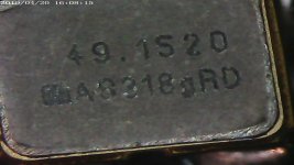
I took some photos today from clocks that was originally in my TransportPiDigi-board. There is label AS318, it looks like same clock that is inside in those Accusilicon metal boxes? Is there any benefic to upgrade to those clocks?
In this post is photo from inside of Accusilicon shielded box:
https://www.diyaudio.com/community/...ultra-low-jitter-clock-gb.356675/post-6706908
In this post is photo from inside of Accusilicon shielded box:
https://www.diyaudio.com/community/...ultra-low-jitter-clock-gb.356675/post-6706908
Attachments

I guess I somehow was wrong in my plan, I thought it was possible to install ROON server on a rasp4, but I was proven wrong😀
So I guess i'll go the simpliest way, RoPieee on the rasp4 2gb that I already own, and a roon endpoint + dac solution based on that.
I'll finally go with the Q7, dac, and move my way to make the best power solution possible. and first buy a soldering solution😀
So I guess i'll go the simpliest way, RoPieee on the rasp4 2gb that I already own, and a roon endpoint + dac solution based on that.
I'll finally go with the Q7, dac, and move my way to make the best power solution possible. and first buy a soldering solution😀
Hi deanorthk,
One of the best and most trouble-free version of roon is ROCK. ROCK is a specialized X86 version (image file) of Linux that acts as the roon server. It installs painfree, and from there a little configuration is required. But, it does require a small computer spec'ed to meet the size of your library. Popular computers to use for this task are the little Intel NUCs SFF, or other equally spec'ed mini computers. When I signed up for roon, this is the way I chose to go. My son and I installed it on a NUC, and have never looked back. Sure it adds a few $$ to your end goal, but it's worth it! Best thing is, it just works in the background, and you should never know it's there. It sits on the shelf in my shop along with may NAS and other servers I have/use. From there, you can create as many end-points as you want based on RPis. This is where Ian's hardware comes in. 🙂
This link will take you to the roon help page where they suggest differently configured NUC hardware. Scroll down to see them. We opted for this one.
Good luck.
Last edited:
Hi Redjr. thanks for the link btw🙂Hi deanorthk,
One of the best and most trouble-free version of roon is ROCK. ROCK is a specialized X86 version (image file) of Linux that acts as the roon server. It installs painfree, and from there a little configuration is required. But, it does require a small computer spec'ed to meet the size of your library. Popular computers to use for this task are the little Intel NUCs SFF, or other equally spec'ed mini computers. When I signed up for roon, this is the way I chose to go. My son and I installed it on a NUC, and have never looked back. Sure it adds a few $$ to your end goal, but it's worth it! Best thing is, it just works in the background, and you should never know it's there. It sits on the shelf in my shop along with may NAS and other servers I have/use. From there, you can create as many end-points as you want based on RPis. This is where Ian's hardware comes in. 🙂
This link will take you to the roon help page where they suggest differently configured NUC hardware. Scroll down to see them. We opted for this one.
Good luck.
I already have a roon server, based on win10 though, with an audiophile ethernet card, an i9 9900KS and a Z490 motherboard, all that in an hdlpex case for dead silent operation. The thing is I wanted to move to a less power hungry thing, while still, if there was a solution, keeping my Jcat ethernet card. AS price for AC are going to rise, rise, rise, I kinda wanted to optimised everything, the move to a rasp dac/streamer is a part of that too, vs my MYTEK Brooklyn Bridge.
Order placed, in two days I'll begin that project of dac/streamer.
Orderd the station Pi pro, the dac, the Q7, the accusilicon clocks, the ess accessory for the dack. That's the first part of the build...
After that, I'll order the PSu section, the soldering base, then the external PSU, and I'll try to get a case were all that could fit🙂
Orderd the station Pi pro, the dac, the Q7, the accusilicon clocks, the ess accessory for the dack. That's the first part of the build...
After that, I'll order the PSu section, the soldering base, then the external PSU, and I'll try to get a case were all that could fit🙂
Hi Redjr,Hello,
Here's a look at my latest DAC/Streamer project. Streamer meets mini-ITX computer case. I've been wanting to do something a little different - mostly because I want to stretch my creative side of design and implementation. Something a bit less mundane in the world of DIY audio gear. Including most of what I've built over the years too! Of course it had to sound great too. I'll try not to be too verbose but stick to the main subsystems.
BTW, I'll be putting a more detailed project writeup article with tons of images up on Hackaday soon. Once complete and ready for public consumption I'll post a link here.
To pull this project off, I had a mental idea of what I wanted to accomplish. I even had a plan that seem to continually change as I went along. The first was finding a suitable enclosure. If you like to build computers, there's never been a better time to find anything as unique as you want to build. Every formfactor is available. So, I went with this one, the Silverstone SG13 mini-ITX case. I needed a case with more height than a standard audio enclosure.
Here's a before and after.
View attachment 1131769
After
View attachment 1131774
At first it was challenging to get all the pieces suitably arranged. Layout was critical in getting everything to fit and make it work with little physical interference. In the end, this is what I thought worked best - at least for me. The case needed to include enough space for all the electronics. I chose to go with the suite of DAC related boards from @iancanada. I have used his kit for other builds, and knew they'd sound great. He offers a wide array of sorted PCBs that do not disappoint. As far as I'm concerned, my digital library has never sounded better!
A complete list of available hardware Ian offers is on his Github and can be found here.
More images of internals placement. A 3rd LinearPi PSU was added in the space in the lower left.
View attachment 1131779
View attachment 1131780
Fitting the transformers to HD bracket that came with the case.
View attachment 1131781
Transformers mounted to top bracket. Shown upside down.
View attachment 1131784
Was able to route most of the AC wiring in the frame rails of the case. It came out really well.
View attachment 1131788
Modding the case and 3D printed back panels. This was the final layout all the I/O and IEC sockets. Sliding door where the I/O shield would normally be. For now anyway. Not sure how that will used - if at all.
View attachment 1131783
Cutting the front panel and fitting the 7" LCD screen. Patience. Used a portable dremel tool with this cutting wheel. Makes quick work of any plastic.
View attachment 1131782
Some final wiring. Anyone spot the error in the next image?
View attachment 1131793
Finished project showing this as a roon endpoint, using the 7" touch panel for transport controls.
View attachment 1131794
A couple items and featured I wanted to include in this build, just didn't happen due to lack of space on the front panel. Version 2 prototype is already being worked on. A smaller 5" screen and a LCD for source selection(wasn't implemented) but some hardware is already in place.
Here is a list of the hardware items I used for this build.
o - 1, RaspberryPi 3 SBC
o - 1, StationPi Pro (integrating motherboard)
o - 1, FifoPi Q3 Ultimate FiFo Reclocker
o - 1, Dual Mono Plus DAC ES9038Q2M Sabre HAT
o - 1, LL1544A Transformer I/V Stage
o - 1, ReceiverPi
o - 1, ConditionerPi
o - 2, LinearPi PSUs
o - 1, LifePO4 Mini PSU (battery)
o - 2, Universal UcConditioners (Super Caps)
o - 2, Triad 6VAC Secd Toroidial Trannies
o - 1, 7" RaspberrPi LCD (the official one)
o - 1, Silverstone SG13 case
o - 1, XMOS USB receiver.
o - 1, Remote Soft switch (customized designed by Jhofland).
o - 1, Software was Roon and RoPieee Bridge
BTW - This project is not for the faint of heart. 🙂 This was entirely different than working in an open bottom case. It was not easy at all. Patience and precision is required. I had several partial do-overs to contend with, and hardly anything went as planned. Design, build and test as you go along!
Next step in testing will be to put into my main system and see how it performs and sounds.
Thanks for looking.
Ps. I was doing some testing on my bench, and turned it on and immediately smelled fresh electronics burning. I hit the switch almost immediately and never did see any magic smoke. So, in my despair I knew it would likely take a complete dis-assembly to find whatever was the culprit. Nothing was obvious visually, but given how it's constructed, you can't see each PCB in full either. Out came the Variac. I first tested the trannies by themselves. All voltages normal, no overheating, no smoke. So far so good. Next was to hook up just the PSU regulator PCBs and test each one separately. Again, all output voltages normal, LEDs lite okay, no sparks, no smell. At this point, I started to take apart each 'stack' to see if I could spot something abnormal. I tested each PCB, again separately, or with the RPi. All of them worked just fine individually. I did not removed the StationPi Pro board but it looked normal, but I did measure the input voltage and all was normal.
So I started to reassemble what I had removed and again tested at each 'phase', so I could test each section with all components. Started with putting the trannies back into their cage and re-installed in the case. All measurements correct. O then re-hooked each PSU board. Fired them all up and nothing abnormal. No smell, no sparks, no smoke. Ok. Now with all PSU in place, I started with the RPi stack, and added each board building from the bottom up, and power it up. I tested to the top, where the RPi was (face down), and everything worked fine. All voltages checked out. Next, I did the same with the audio stack. FifoPi first, normal appearing. Next the DAC, still nothing abnormal. The last board was the transformer I/V board. All good. With everything put back together, I slowly brought up the voltage on the Variac to 120VAC. All PCB LEDs were lighting up. No snap, crackle or pop. With everything wired back together as a whole unit, I re-checked the voltages and all were normal.
I plugged up the ethernet cable and let it boot into RoPieee. Fired up Roon on my PC and music came back to life. That was earlier today. But, before I put the cover on, with everything secured down, I took the unit in both hands, and gave it little mild shake upside down, and out fell a 4mm nut. Not saying it was the cause, but I've had it running most of day, even while I write - where I could keep my eye, and nose on it - and it's been playing fine, and sounding no different. I may never know what caused the smell, and maybe I hit the off button soon enough before it could cause any real physical or electrical damage. But, it will probably bother me, because that intense of a smell usually means something is getting cooked and rather quickly too. 🙁
Wow what a nice build I was wondering if you are using a isolation transformer (1 on 1) in your build, I am wondering this in general since I have not seen a lot of isolation transformers between the mains and the trannies in this forum. Does it make sense to use one if using the linear pi's with UcConditioners? What would be the pro's/con's when using one.
Cheers
FWIW I experimented with isolation transformers with the thought of reducing noise on the AC, aka a power conditioner. Two conclusions. It made a very small change in sound. Can I really hear a difference? I concluded I could hear a slight change and it was for the worse so I took it out. I tried both an EI type transformer and a very large toroidal. IMHO, if you do not have one on hand, then save your money. I use them in my workshop for safety when testing my builds.
I have received my order, and I've staked the parts I have ordered on the SuperPi pro. Those are really quality product, the PCB is impressive, and I couldn't really see based on the video or pics, how actually small everything is!
Now, the next step before I order the power supply stuff : the soldering unit!
Now, the next step before I order the power supply stuff : the soldering unit!
Thanks for you info 👍FWIW I experimented with isolation transformers with the thought of reducing noise on the AC, aka a power conditioner. Two conclusions. It made a very small change in sound. Can I really hear a difference? I concluded I could hear a slight change and it was for the worse so I took it out. I tried both an EI type transformer and a very large toroidal. IMHO, if you do not have one on hand, then save your money. I use them in my workshop for safety when testing my builds.
- Home
- Source & Line
- PC Based
- IanCanada's Latest RPi GB Goodies Impressions... and your tweaks, mods and hints...