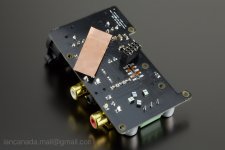
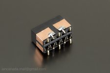
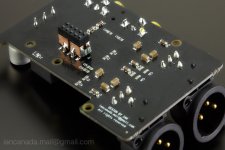
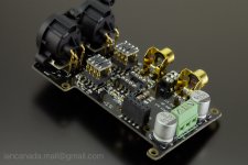
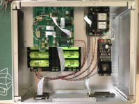
i have all of them powered individually by batteries, one 3.3v from the current battery management board, the other two 3.3v from ian's single battery management board
DocumentDownload/PowerSupply/BatteryManagementBoard at master * iancanada/DocumentDownload * GitHub
DocumentDownload/PowerSupply/BatteryManagementBoard at master * iancanada/DocumentDownload * GitHub
How far back....
Speaking of PSUs and the various individual voltages that must be supplied across the RPi, FiFoPi, DAC, and I/V Std boards.... How 'far back' down the chain to the original xfomer must these regulated voltages go before they should begin with their own separate xfomer, or SMPS?
I currently have a single xformer that has taps for 15-0-15 and 9-0-9 output. All the digital voltages are rectified and regulated from the 9-0-9 secondary. The Output stage is rectified (and filtered) from the 15-0-15 secondary, with final regulation being done by the Jung-Didden Super Regulator. I'm also using a SilentSwitcher (Didden) to supply the necessary input voltage of 6.5VDC to the NewClassD regulators for; DVCC and VCCA. A TP Trident SR is used for AVCC.
RPI is stilll using a quality (iFi), SMPS wall-wart, but will get changed out during final assembly.
So far I'm very happy with the sonic quality of this arrangement, but just wondering if totally separate PSUs are warranted, or should be used for added quality of the entire Ian 'DAC stack'.
My question is; Should the single xformer really be two separate xformers to eliminate and galvanic interference between the digital and analog supplies?
My question is; Should the single xformer really be two separate xformers to eliminate and galvanic interference between the digital and analog supplies?
One transformer should suffice. An R-core is good to help minimize AC power line noise coupling. A transformer with perhaps +-15v or +-16v and one or two 9v (or lower, but not lower than 5v) windings. It can be better if the +-15v windings are separate rather than having one center-tapped winding. That way you can decide where the grounds will be tied together.
A linear supply for RPi, if you want that too, might be best on a its own separate R-core transformer.
Last edited:
I just received Youtube recommendation that new Raspberry Pi 4 is out and avaiable!
Specs:-
Broadcom BCM2711, Quad-core Cortex-A72 (ARM v8) 64 bit SoC @1.5GHz
1GB, 2GB or 4GB LPDDR4-2400 SDRAM (depending on model)
2.4 GHz and 5.0 GHz IEEE 802.11ac, Bluetooth 5.0, BLE
Gigabit Ethernet
2 USB 3.0 ports, 2 USB 2.0 ports.
40 pin GPIO (fully backward compatible with previous boards)
H265 (4kp60 decode) and H264 (1080p60 decode)
2 x micro HDMI port ( up to 4kp60 supported)
OpenGL ES 3.0 graphics
Micro-SD card for OS and storage
I have ordered one isolatorPi with u.fl cables, but I have yet to receive them (finger crossed I will get it because I opted for non-registered mail to save cost).
I hope isolatorPi will still compatible with new release Rpi 4.
Got the ll1674 working. Set up with 221r resistors.
An interesting listen, much the same difference as I've heard going from an active pre to an MFA transformer pre. Smoother, more relaxed but a little dynamically restrained. I cant hear any difference in the treble, I'm good to 16.5k so maybe any roll off is above my hearing range. The bass is maybe a tiny bit more damped, pillow in kick drum kind of thing.
Overall quite a subtle change, I could comfortably live with either. The question is do I strip back the unused 13v rails to give 2 additional rails for the dac board?
@sq225917
Separate rails are always better than sharing 🙂.
Please let me know if you have update.
Regards,
Ian
I need to order a decent set orf side cut pliers first....
You can just cut the "in" track with a scalpel or similar. That leaves you more local decoupling options.
Implement Greg's Rasmussen filter
I implemented Greg suggested Rasmussen filter for my I/V STD in this way. I'm pretty happy with the solution. Please find the pictures for details.
It needs to be run-in it for a couple of days before doing any listing test.
Ian
I implemented Greg suggested Rasmussen filter for my I/V STD in this way. I'm pretty happy with the solution. Please find the pictures for details.
It needs to be run-in it for a couple of days before doing any listing test.
Ian
Attachments
Ingenious Ian!
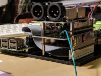
I've separated my Pi from the stack as suggested previously with a ribbon cable and used a spare transfomer IV pcb for a screen between the DAC and the FiFoPi.
I scraped a little solder resist off the ground plane and soldered a ground wire, despite a few tracks on it I think there's still a lot of screening. This definitely reduces the remaining slight grain and makes the presentation a bit smoother. The only downside is that two of the mounting holes are now blocked by the IDC connector. A bit of decent double sided foam tape solves that.
It also makes sourcing an enclosure easier with reduced stack height 😀 I'm getting close to putting this in a box and just enjoying it. I found the player a bit grainy and shouty at first and struggled with bad recordings (I have loads of those!) but as we have gone along and developed these tweaks, it's got to the point where I can just put something on and just listen. Thanks to all the contributors and especially Ian.
Attachments
Last edited:
Ian, so is that just an RC filter between r-rb and another between l-lb? If so what are the values?
Also could it be included onto a seperate shield board with full ground pours?
Also could it be included onto a seperate shield board with full ground pours?
Low budget shield board would be to cover a board with aluminum foil, and ground the foil. You could also use copper tape, but copper tape is not cheap these days.
I've made shields with copper tape, then cover the tape with kapton tape so there is no risk of shorting to something.
I've made shields with copper tape, then cover the tape with kapton tape so there is no risk of shorting to something.
Low budget shield board would be to cover a board with aluminum foil, and ground the foil. You could also use copper tape, but copper tape is not cheap these days.
I've made shields with copper tape, then cover the tape with kapton tape so there is no risk of shorting to something.
I'm trying to design a shield HAT to be installed under DAC HAT. Maybe I could share some once I have the prototype PCBs.
Regards,
Ian
For us can i use trasfomer LL1527 ? Thanks for help
LL1527 is 1+1:1+1. It can be configured as 1:2, but we need at least 1:4.
You can try it but the output voltage level will be 6dB to 12dB lower.
Ian
I'm trying to design a shield HAT to be installed under DAC HAT. Maybe I could share some once I have the prototype PCBs.
Regards,
Ian
That would be great.
Done, no magic smoke.
Doesn't sound better yet, going to let it run through a few full charge cycles of the lifepo to let the new cap after the reg settle in.
I have a suspicion that canabalising the iv rails to make two new rails for the dac board with local supercaps and stick to the transformer iv might be the way forward.
We'll see...
Done, no magic smoke.
Doesn't sound better yet, going to let it run through a few full charge cycles of the lifepo to let the new cap after the reg settle in.
I have a suspicion that canabalising the iv rails to make two new rails for the dac board with local supercaps and stick to the transformer iv might be the way forward.
We'll see...
When I separately powered ths avcc line the difference was immediate: more smooth highs less grainy.
I am interested in your findings after run in.
It took a few hours to get there, supercaps needed running in, but yes its noticeably better, less grainy overall, reduced glare. Closer to good analogue. Ill do another rail tomorrow
- Home
- Source & Line
- PC Based
- IanCanada's Latest RPi GB Goodies Impressions... and your tweaks, mods and hints...
