@ichiban,
In planning my own use of these adapters, I have been planning to put the adapter on top of the stack of RPi -> FiFoPi -> Ian's GB DAC and then the TP I/V stage on top of that.
You're planning to do it differently?
Greg in Mississippi
Bottom up, Mercury, Ians Adapter, Ians dual 9038 dac, FiFoPi Ultimate, RPi 3.
Attachments

hello all, i received all the boards !!!
i´m going to upgrade the stock clocks on fifopi, i have the ians dual 9038 dac and planing to run in synchronous mode.
the stock clocks are 45.1584/49.1520 MHz.
Should i buy CCHD-957 crystek 45.1584/49.1520 MHz or other frequencies??
what is the best sound quality?
thks,
Nuno
i´m going to upgrade the stock clocks on fifopi, i have the ians dual 9038 dac and planing to run in synchronous mode.
the stock clocks are 45.1584/49.1520 MHz.
Should i buy CCHD-957 crystek 45.1584/49.1520 MHz or other frequencies??
what is the best sound quality?
thks,
Nuno
I'm interested in using 4 ultra/super capacitors on the DAC hat board. However, I can't seem to find any specs on the batteries in the docs other then 3.3v. Is there a preferred brand/part number of a cap to use? Mouser or Digi-key? Has anyone fitted these caps on the DAC and willing to share a picture?
Last edited:
hello all, i received all the boards !!!
Should i buy CCHD-957 crystek 45.1584/49.1520 MHz or other frequencies??
what is the best sound quality?
Two known good clocks are the Crystek you mentioned and the NDK SDA series which can be bought at diyinhk. You'll need Ian's adapter for both. As to which one is best that is system and taste dependent so try them and hear for yourself. That's part of the fun.
I'm interested in using 4 ultra/super capacitors on the DAC hat board. However, I can't seem to find any specs on the batteries in the docs other then 3.3v. Is there a preferred brand/part number of a cap to use? Mouser or Digi-key? Has anyone fitted these caps on the DAC and willing to share a picture?
@redjr,
I didn't specify the P/N of those optional super capacitors. I just listed the size in the user's manual. You can try any in the same size and let me know what are you prefer.
If any one has good result with those optional super capacitors, please share your experience with us.
Have a good night.
Ian
Crystek clocks
Hi,
I have two Crystek clocks on my Twisted Pear Cronus pcb.
I find the pins line up exactly with the pins on the fifopi ultimate.
Will these function properly on the fifo? I see that there are clock
carriers from Ian that have extra capacitance.
-ICHI
Hi,
I have two Crystek clocks on my Twisted Pear Cronus pcb.
I find the pins line up exactly with the pins on the fifopi ultimate.
Will these function properly on the fifo? I see that there are clock
carriers from Ian that have extra capacitance.
-ICHI
Hi Ichiban,
Of course you can : it provides you a side to side proper benchmark of the two family of crystals as there is no extra decoupling caps from Iancanada's adaptaors.
Notice the CCHD-957 has its own oscillator board embeded with the caps.
The Iancanada last adaptator board is certainly an improvment because it was measured in relation to both the CCHD-957 & the Fifopi board.
regards
Several response...
@spm / @ ichiban, quickest & easiest solution on the interference with the Mercury caps is to us longer headers between the I/V board and the adapater to increase the space between the boards. I did this in setting up my TP I/V boards even with the I/V board on the top of the stack, to give me more space to mount the clock and AVCC local regulator boards on my TP Buff-IIIPro builds..
@pistollero, ACTUALLY to run in full-sync mode, you need 128fs... for 44.1/48, that is a 5.6488/6.144 pair. You can run them in sorta-sync mode with a 45/49 pair however, I am doing that now.
As for Crystek CCHD-957 or NDK SDA's some will prefer one and some the other. AND I understand the lack of local decoupling caps or what decoupling caps are used will also change the sonics. I haven't experimented with decoupling caps yet, but have tried both the Crystek and NDKs. IN MY SYSTEM, TO MY EARS, AND ACCORDING TO MY PREFERENCES, I have been preferring the NDKs. BUT I have a lot of power, coupling cap, and I/V combos to try yet and that may not hold true for all combinations and certainly not for all users and their setups. BOTH are very good. YMMV.
Ian's new adapters are designed for the Crystek CCHD-957. You can fit the NDK's on his earlier adapters. I soldered up several sets last night. I did them all by hand... NDK's on the old adapters are easy, you just lightly tin one mounting pad, line the clock up PERFECTLY and hold it down with something like a small flat screwdriver, then flow that pad / clock corner to tack it down. THEN go over and solder each of the other corners.
ALWAYS make sure to position pin 1 in the right quadrant first before soldering!!! This goes for both the NDK and Crysteks.
I use the PCB pieces removed from the new clock adapters as spacers when soldering in the mounting pins to make sure the clock adapter assemblies with Crystek clocks are sufficiently low-profile to fit under the DAC board. I took some pix of that last night, I'll see if I can get them up tonight. With Ian's older adapters and Crysteks, you have to trim and mount the pins before mounting the clocks... I took a picture of that too.
AND I cover the top of the Crysteks with a layer of Kapton tape to make sure I don't get shorts by accident.
Soldering the decoupling caps is not too hard either with good eyes, steady hands, and good solder. I lightly tin one pad, position the cap and hold it down again with a small flat screwdriver or if my fingernails are sufficiently long, my thumbnail or index finger nail. THEN I use a VERY FINE soldering iron tip to flow that tin and tack down the cap, solder the other side, then touch up the first side. Repeat for the remaining caps. This is a LOT easier to do before you mount the pins!!!!
@redjr / @iancanada, I planned to try the same supercaps that Joe Rasmussen suggested in his thread here:
Practical Implementations of Alternative Post-DAC Filtering
Allo.com uses them on their Boss, Boss 1.2, & Katana to good effect. I have used them on my RPi's, Ian's IsolatorPi, Allo's Kali, and other RPi DACs, along with my SDTrans384. The good thing about them is they are .33F/5.5V units so have a wider range of uses. The BAD thing is they are EOL at Panasonic, so if we find more, buy some now. I'll post PN tonight with the pix.
Of course, I am curious if they will make much of a difference with a direct-connected LiFePO4 or Ultracap supply. I'm guessing not, but we will see / hear.
Greg in Mississippi
Result
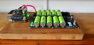
Got my setup running for over a week now and it's an overall BIG update!
I was looking for a setup that could bring more details in the midd audiostage. And it did! Even better, from highest to the lowest tones, everything sounds brighter, tighter and more alive.
My setup:
LifeP04 - Rpi - FifoPi + Crystek CCHD-957 - ESS Controller - ES9038Q2M DAC HAT - STD OPA outputstage + Burr Brown OPA2134PA opamps
Added some pictures just for showing off
Attachments

I have lift-off! Beautiful music. I had two different orders with Ian and the 2nd package showed up yesterday. After meticulously getting my PSUs sorted out and the necessary voltages I needed for each, I started stacking everything together. For now, I'm simply using a single 3.3v supply to the DAC, but may decide to break out the 3 sections at a later time. I also decided - for now - to go with the default I/V stage opamps. While running on my bench, they do seem rather warm to the touch though. Is that normal? For now - just to get everything up and running quickly, I'm using a micro-USB for the pi power. Presently I'm using a multi-tap r-core tranny with a couple of regulator boards from DIYINHK for the required 5.0 and 3.3 voltages. I need to order one more for the I/V stage.
After getting everything stacked properly and double checking the polarity of all connections, I booted up the RPi and then the FiFo/DAC/ESS Cntrl/Output PCBs. Next was to configure RoPieee (roon) for a HiFiBerry DAC. No music! Say what? After re-reading the manuals (Great job on the docs. Thanks Ian & Greg), I noticed that I needed to switch #1 on the FiFo to on. I think this is also a configuration option I can change in roon. Once I changed the switch setting, assembled everything and the music flowed. Listening to it now as I type this.
Next step is to replace the clocks and try the OPA1612/22 opamps on the adapters. I guess I'll have to try my hand again at SMD soldering. I also want to try the ultra caps (@Greg - thanks for the link.)
All I can say is thanks to Ian for bringing this project (relatively affordable) to life and making it available to the DIY community. It is very configurable and extendable with minimum amount of hassle. Lots of options for upgrading.
Thanks again. Off to do more listening.
Oh, the Apple remote compatibility is a nice touch and extra. I had one one hand. 🙂
Last edited:
@spm / @ ichiban, quickest & easiest solution on the interference with the Mercury caps is to us longer headers between the I/V board and the adapater to increase the space between the boards. I did this in setting up my TP I/V boards even with the I/V board on the top of the stack, to give me more space to mount the clock and AVCC local regulator boards on my TP Buff-IIIPro builds..
@pistollero, ACTUALLY to run in full-sync mode, you need 128fs... for 44.1/48, that is a 5.6488/6.144 pair. You can run them in sorta-sync mode with a 45/49 pair however, I am doing that now.
As for Crystek CCHD-957 or NDK SDA's some will prefer one and some the other. AND I understand the lack of local decoupling caps or what decoupling caps are used will also change the sonics. I haven't experimented with decoupling caps yet, but have tried both the Crystek and NDKs. IN MY SYSTEM, TO MY EARS, AND ACCORDING TO MY PREFERENCES, I have been preferring the NDKs. BUT I have a lot of power, coupling cap, and I/V combos to try yet and that may not hold true for all combinations and certainly not for all users and their setups. BOTH are very good. YMMV.
Ian's new adapters are designed for the Crystek CCHD-957. You can fit the NDK's on his earlier adapters. I soldered up several sets last night. I did them all by hand... NDK's on the old adapters are easy, you just lightly tin one mounting pad, line the clock up PERFECTLY and hold it down with something like a small flat screwdriver, then flow that pad / clock corner to tack it down. THEN go over and solder each of the other corners.
ALWAYS make sure to position pin 1 in the right quadrant first before soldering!!! This goes for both the NDK and Crysteks.
I use the PCB pieces removed from the new clock adapters as spacers when soldering in the mounting pins to make sure the clock adapter assemblies with Crystek clocks are sufficiently low-profile to fit under the DAC board. I took some pix of that last night, I'll see if I can get them up tonight. With Ian's older adapters and Crysteks, you have to trim and mount the pins before mounting the clocks... I took a picture of that too.
AND I cover the top of the Crysteks with a layer of Kapton tape to make sure I don't get shorts by accident.
Soldering the decoupling caps is not too hard either with good eyes, steady hands, and good solder. I lightly tin one pad, position the cap and hold it down again with a small flat screwdriver or if my fingernails are sufficiently long, my thumbnail or index finger nail. THEN I use a VERY FINE soldering iron tip to flow that tin and tack down the cap, solder the other side, then touch up the first side. Repeat for the remaining caps. This is a LOT easier to do before you mount the pins!!!!
@redjr / @iancanada, I planned to try the same supercaps that Joe Rasmussen suggested in his thread here:
Practical Implementations of Alternative Post-DAC Filtering
Allo.com uses them on their Boss, Boss 1.2, & Katana to good effect. I have used them on my RPi's, Ian's IsolatorPi, Allo's Kali, and other RPi DACs, along with my SDTrans384. The good thing about them is they are .33F/5.5V units so have a wider range of uses. The BAD thing is they are EOL at Panasonic, so if we find more, buy some now. I'll post PN tonight with the pix.
Of course, I am curious if they will make much of a difference with a direct-connected LiFePO4 or Ultracap supply. I'm guessing not, but we will see / hear.
Greg in Mississippi
Thks for the help. so i can buy 5.6488/6.144 pair for true sync mode? Did you tried?
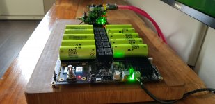
Got my setup running for over a week now and it's an overall BIG update!
I was looking for a setup that could bring more details in the midd audiostage. And it did! Even better, from highest to the lowest tones, everything sounds brighter, tighter and more alive.
My setup:
LifeP04 - Rpi - FifoPi + Crystek CCHD-957 - ESS Controller - ES9038Q2M DAC HAT - STD OPA outputstage + Burr Brown OPA2134PA opamps
Added some pictures just for showing off
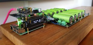
@Maui
Very well built/finished system. Better than mine😀. Congratulations!
If it is possible, try the balanced output. Because my main system is balanced, so my gears are more optimized to balanced output.
Or, try transformer I/V stage, or my later on OPA861 I/V stage. I'm looking forward to your new update.
BTW, I like your hard wood base, the brand is similar to something in our kitchen, .... the knife😀
You took very good pictures, what the lens did you use?
Regards,
Ian
Thx Ian, it took a lot of patience to line it all up this tight but I am very happy with the result. Next step is to cover it all up with some kind of transparent cover, just to keep dust and kids out. Not sure yet how to do this, bit worried about head building up inside.
I sadly cannot try the balanced output because my amp has no balanced input. The transformer IV stage is waiting for a bit more budget. It will be the next update, but I find the transformers a bit expensive for now. 😱
You're right about the knife brand, makes a nice base don't you think 🙂
About the pictures & lens... I made a few quick pics with my phone (samsung S8). They came out better then I expected 😀
Hi Ian,
Parcel arrived safely, today.
I really appreciate your efforts for this GB.
Regards,
atom
Parcel arrived safely, today.
I really appreciate your efforts for this GB.
Regards,
atom
Debugging question
So close to nirvana but not quite there.
I am using the FIFOPi with Volumio to Ian's I2StoPCM to a 1541a DAC.
It is powered by 2 PS. One is a +5v linear supply with a Salas shunt to the clean side of FIFOPi. The second is a linear +5v 2A supply to the dirty side of the FIFO.
The system appears to function flawlessly, but no sound. It boots up, finds the NAS plays tracks, selects the correct clock. LED's in the FIFOPi correctly indicate I2S on the input and the output. The I2StoPCM LED's however initially lit up with the aux & power, but no I2S lock. I checked continuity and it appeared the ufl connectors are connected. But after fiddling around it seemed I got all 3 LED's to light up on the I2StoPCM. But when I got connected to the rest of the system and repowered up, the I2StoPCM was back to aux & pwr but no I2S lock.
Here is the wildcard. I initially connected the PS to the dirty side of FIFOPi with 12v and fried the Pi. I replaced the Pi but am using the same FIFO. All appears well as described, but again no sound and strange behavior with the I2StoPCM LEDs.
My basic question is with the FIFO appearing to work perfectly from according to the LED's can I assume it is ok? If I had not fried the Pi I would be convinced I have a bad ufl cable. I will try swapping in some other cables. But am I chasing the wrong thing and should replace the FIFO?
I am pretty sure I have the ufl cables connected correctly.
BCK - BCK, WS - LRD, & SD - SD
All suggestions welcome.
Attachments
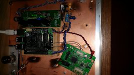
Did you not forgett the Masterclock uf-l wire between the FiFoPi and the I2StoPCM board 😉
Absolutely I did forget the Mclk!! I knew a smart set of eyes would see something that I missed. I'll let you know if that gets me going. Thanks
Big thanks to diyiggy
Connected the Mclk and it fired right up. I really had a blind spot for that one and would have run in circles and still missed it. Many thanks diyiggy.
Also many thanks to Iancanada for this fine piece of engineering and great service to the community.
It is way too early for me to comment on sound other than to say I am impressed how good it is on the supplied test clocks. Very clear. After the system breaks in I will install the NDK SDA OX and the normal 1541a chip getting me back to the base I am used to. While I was testing I pulled out the 1541 S2 chip I normally run. I did not want to risk the S2 while I was messing around with power supplies. Also look forward to playing with 3.3v supplies. Might find a use for my stock of supercaps 🙂
Massive thanks to Iancanada. I am very pleased with the design. I like the extensive use of LEDs to let us know what is actually happening without a scope. I also think the layout is a work of art. Very professional. I like the way it fits on the Pi.
And again, thanks for all the work to run this GB and bring us great tech at really great price.
Help needed.
I assembled LifeP04 - Rpi - FifoPi + ESS Controller - ES9038Q2M DAC HAT (in async mode) - STD OPA outputstage but I'm getting no sound. The ES9038Q2M locks the signal but the ESS Controller states it has no input. I also tried sync mode with the u.fl cable. I get locks on the ES9038Q2M but still no input. When I connect an external dac to the FifoPi with an I2S connection it all works. When I connect the ES9038Q2M directly to a rpi it all works. Something in the connection between the FifoPi and the ES9038Q2M seems not to be in order?! Or am I missing something? /proc/asound/card0/pcm0p/sub0/hw_params is existing and has data.
Big Bird.
Last edited:
Help needed.
I assembled LifeP04 - Rpi - FifoPi + ESS Controller - ES9038Q2M DAC HAT (in async mode) - STD OPA outputstage but I'm getting no sound. The ES9038Q2M locks the signal but the ESS Controller states it has no input. I also tried sync mode with the u.fl cable. I get locks on the ES9038Q2M but still no input. When I connect an external dac to the FifoPi with an I2S connection it all works. When I connect the ES9038Q2M directly to a rpi it all works. Something in the connection between the FifoPi and the ES9038Q2M seems not to be in order?! Or am I missing something?
Big Bird.
Please disable the auto mute function by setting jumer switch on your ESS controller and let me know if issue is fixed.
Regards,
Ian
- Home
- Group Buys
- Ian asynchronous I2S and S/PDIF FIFO KIT group buy