You could try the LM4562 which is available in SMD. I like the OPA2604 when implemented correctly so either something is going amiss or you just don't like the subtleties of the OPA2604's presentation.
http://www.diyaudio.com/forums/anal...u-have-checked-see-its-stable-havent-you.html
Also, try attaching your picture directly 🙂
To add a photo, files or non standard files.
First click "go advanced" in the box below the "quick reply" message box. Doesn't matter if you decide half way through a message to do that, it carries it foward.
Then click "Manage attachements". Maximise the new Window so that you can see all the text.
Click browse in the first box at the top and find your picture. Repeat for any more pictures.
Click upload... a message appears "uploading"
When complete the files will show as being attached. Now click the small text that says "close this window"
The pictures should now be attached and when you submit your post they will appear.
Make sure your pics aren't too big, a couple of 100k is plenty, and many members object when they are massive and it alters the margins
It tells you in the attachments window what max sizes are allowed.
If you want to attach a file that has a non standard format for example excel, circuit simulation etc then try putting the files in a zipped folder and attaching that.
Mooly,
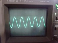
Thank you very much for your advice to add images, is the first image you insert.
If the assembly is stable. Not the first time I ride the OPA2604 with good results, but this time it was not so.
In the output stage OPA275've ridden. it also has a good sound.
Thank you very much for your advice to add images, is the first image you insert.
If the assembly is stable. Not the first time I ride the OPA2604 with good results, but this time it was not so.
In the output stage OPA275've ridden. it also has a good sound.
Definitely worth trying a filter, even with TDA1541A. Its definitely also worth bringing up the droopy top end by some means. You could do that by adding on two more TDA1541As (if you're feeling fairly rich) and feeding them with an HEF4517 delay line to create a 3 tap FIR filter. Thorsten also says undoing the droop is definitely worthwhile, I think he does it by some passive LC circuit, though not sure of the details.
Actually i have a small collection of tda1541a chips, so i could try the 3tap fir filter. But that seems a long term project.
For the time being, i will try the filter (not the amplification) stage as pictured here. http://www.diyaudio.com/forums/tubes-valves/197920-thorstens-tube-stage-tda1541a-6.html#post2747723
What do you think of that one? Seems a lot less complex than the one you described earlier (7th order elliptical).
What is your view on the adverse effects on phase?
Well I've tried caps (in this schematic, C2) to ground and haven't liked the sound. But then I've not tried with TDA1541A. The filter is only first order and you do need a very clean ground to connect that cap to - unfortunately its driven by a high speed DAC and hence the routing of that ground is crucial. I doubt I ever got it right 🙂 So while it will correct the droop with that LC tank (which my elliptic doesn't) it won't filter glitches very severely. Which is probably fine when you have a valve following it, but not so good for SS.
As for phase effects, subjectively haven't noticed any even though the phase performance of my elliptic filter isn't so hot at the top end. Lots of group delay above 10k or so. I read somewhere that to be audible the group delay around 10k needs to be something like 2mS, I think my filter gives less than this.
As for phase effects, subjectively haven't noticed any even though the phase performance of my elliptic filter isn't so hot at the top end. Lots of group delay above 10k or so. I read somewhere that to be audible the group delay around 10k needs to be something like 2mS, I think my filter gives less than this.
i am runnig my dac now non-oversampling without any filtering. Quite happy with it, but i do hear a recessed top-end. This would probably for me be the objective of adding a filter: compensate the roll-off towards 20khz.
The elliptical filter, and its steep cutoff would be more aimed at the (anti)aliasing effects beyond 20khz i would presume.
The elliptical filter, and its steep cutoff would be more aimed at the (anti)aliasing effects beyond 20khz i would presume.
The purpose is two-fold, yes definitely to attenuate the image frequencies - it has better than -50dB stop band. But I reckon (still have to simulate this to verify the hypothesis) that even a totally glitch-free DAC generates broadband noise just by virtue of having a finite settling time between output states. The filter severely limits the extent of this noise - the subjective effect being a considerable soundstage depth improvement (on TDA1545A).
That looks OK, but you don't like the sound 🙂
All you can do is try other alternatives. The good thing is that you can identify differences and know what "kind" of sound you want. My experience of the OPA2604 has been good and so to the OPA2134.
I don't know what else to suggest to you. Maybe the "Excaliber" TLE2072 which based on the TL072 but with high drive ability.
Thanks Mooly
I've always had good experiences with the OPA2604, and has been my first choice. Maybe the problem is in the coupling between the two operational bridge, is a very common mounting Technics players with high-end linear DAC, I have not seen in other manufacturers. 🙄
I've always had good experiences with the OPA2604, and has been my first choice. Maybe the problem is in the coupling between the two operational bridge, is a very common mounting Technics players with high-end linear DAC, I have not seen in other manufacturers. 🙄
Attachments
I've never seen that configuration before used with opamps. Its very like the Class AA ? Technics and Aubrey Sandmans Class S power amps.
I looked up the data sheet on the M5238 and its a high current output device which makes sense given the low values of "R" in the bridge.
The TLE2072 I mentioned has an 80 ma drive ability and operates on supplies down to -/+2.5 volts. Try it 🙂 No guarantees though.
I looked up the data sheet on the M5238 and its a high current output device which makes sense given the low values of "R" in the bridge.
The TLE2072 I mentioned has an 80 ma drive ability and operates on supplies down to -/+2.5 volts. Try it 🙂 No guarantees though.
On Wednesday Farnell ordain in the units required, and will try this weekend.
Thanks, and Merry Christmas
Thanks, and Merry Christmas
Hi,
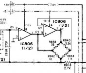
After studying the mounting understand that this is a Howland current pump, modified where the first operational amplifier acts as voltage and input impedance adapter (infinite), and the second operational amplifier makes the voltage at constant stream, with a ratio 1/100, with a low impedance Zo...... It maintains the output current constant, varying only the voltage, irrespective of variations in the load, minimizing signal distortion
In this way the op amp that is used is not important. What is important is the relationship of voltage and current in the circuit. The key point to remember is that an Op Amp will use all his considerable open-loop gain to maintain both their investment and non-inverting inputs in line with each other, ie, in the line voltage. If the positive input of the OpAmp see 1V, then its negative input 1V to do well. If the input signal is 0 V, then the output voltage of the circuit should also be above 0 V as the voltage only SRAM maintains two inputs to the same voltage accurately. 🙄
Attachments

Last edited by a moderator:
I'm not convinced 🙂
I still think the current drive ability of the opamp is important although I can't see the rest of the circuit.
In your other diagram, (which I'm going to have to delete because its under copyright from Rod Elliots site, Elliott Sound Products - The Audio Pages (Main Index) you show the voltage output of the opamps "across" the low impedance bridge and so the opamps driving ability must come into the equation. If the second opamp output is at 10 volts then you can either say that 10 volts is across the low impedance of Rload and R3 or, if you say that the first opamp contributes to "raise" the voltage at the junction of Rload and R3 then that first opamp drives a low impedance load.
I think it matters given the impedance values in the circuit 🙂
Yes, you sure you're right
The operational capacity to supply current must be important in this circuit, especially because the designer chose originally an operational with capacity to deliver 50mA, which is beyond the capacity of 2604.
The operational capacity to supply current must be important in this circuit, especially because the designer chose originally an operational with capacity to deliver 50mA, which is beyond the capacity of 2604.
I agree George, opamps for I/V just do not deliver transparency. I have changed my view based on experience, because I used to go for them a few years ago. Try a passive filter (steep one, based on inductors and capacitors) before discrete I/V and prepare to be surprised 🙂 (Listening to passive I/V, 7th order elliptic filter now, can't go back).
In a few places I read that it is important to isolate the DAC output from reactive loads like LCR filters. I do not know the details.
Hi Mooly
These two weeks, I've been testing, measuring ... and many drunkenness
These are my conclusions, and a final thought:
- The OPA 2604 has been for a long time, my first choice when it came to stage I / V in dual SMD circuits operational. But this project has been inappropriate ... Why?? ... I do not know.
- The TLE2072, did not fulfill my expectations, not bad, but not quite like it sonically, I can not say it was worse than the 2604 bid, just different... not for me.
- From there, I decided a radical change, I decided to ride in stage I / V the AD8620ARZ, and in the next step the AD8066, a total of 8 chips with 16 operational ... radically changed the sound better: great dynamic, balanced bass, and high frequencies present without fanfare .... a revelation.
At the same time, I was riding a TDA1541 dac of analogmetric, but using only the PCB, and original components, and of the highest quality that money can buy... no counterfeit Chinese components or factory rejects, made in china.
All bought from Farnell to make sure they are not fakes. And instead of riding the OPA627 expected, I tried to make out with 6SN7 tubes (NOS Sylvania from 1954 year) in SRPP assembly, and the sound was more compact, not worse ... distinct, pure, and liked it, but it made me think ....
Why operational circuits used to color the sound?
My first option if it is a mounting DIP8, no SMD is the OPA627, but in this case the tube output is better.
I'm thinking the end of the tube DAC, and use it for the CD player, different sounds are the player's DAC with four BB PCM56, and the TDA1541 with tubes ... I suspect that everyone will be more appropriate for each type of music I listen to at all times.
The TDA1541, SAA7220 and Marantz players come from, and the CS8412 also original (not Chinese) I bought in little diode
- Status
- Not open for further replies.
- Home
- Source & Line
- Digital Source
- I/V using opamps