Masking tape also works fine, especially for experimental transformers. Soaking the windings with glue or varnish will increase capacitance, true, but I don´t think it will be much of a problem in low-impedance transformers for solid state circuits. I always coat the windings in my tube OPTs with either epoxy or shellac and they all go way past 20kHz.
Funny that this thread appeared today, I´m currently digging through Susan Parkers thread about transformer coupled SS amps.
Funny that this thread appeared today, I´m currently digging through Susan Parkers thread about transformer coupled SS amps.

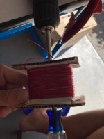
I was hoping to get some missing parts for a tube amp project before the weekend but when they didn´t show up I had to come up with something else to do. A pair of ridiculously small transformer cores and some leftover magnet wire came to my rescue, and just a few hours later I had an operational circuit on my workbench, errr, living room table. No listening tests done yet, I´ll see if I can find some better mosfets and build a stereo prototype first:
Attachments
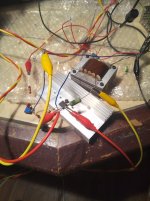
At 13V and 1A bias I get 2,5-3W into 8 ohms between 30Hz and 35k or so. The transformers are scramble wound with two bifilar windings although the primary has been snipped off at 30% to get some local feedback around the mosfet, resulting in ~8dB gain or so.
Weird, that looks like a choke-loaded Nemesis without any additional resistance on the drain or secondary. Or a MoFo with output to a trafo. I don't see the choke in the picture though, it shares a core with the OPT? Wild, man.I was hoping to get some missing parts for a tube amp project before the weekend but when they didn´t show up I had to come up with something else to do. A pair of ridiculously small transformer cores and some leftover magnet wire came to my rescue, and just a few hours later I had an operational circuit on my workbench, errr, living room table. No listening tests done yet, I´ll see if I can find some better mosfets and build a stereo prototype first:
Edit: Based on the photo I think there's a parallel drain resistor missing from yr schm. Also nice trafo potting. What do you use, wax?
Last edited:
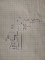
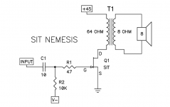
ranschdow: There is no choke involved, just a transformer where the primary winding is split into two sections so that 30% goes between source and ground and the other 70% between drain and rail. Over at the Tubes forum we call it CFB or cathode feedback, it´s an old trick to make a mediocre tube behave like a very good tube, or in this case to make a lousy mosfet behave like a mediocre tube 😀
Re. the potting, I just put them in a jar of varnish and sucked the air out with a meat marinator 😀
The plan was to make a pair of nice layer wound transformers (with grocery bag insulation, of course) but I got lazy.
Re. the potting, I just put them in a jar of varnish and sucked the air out with a meat marinator 😀
The plan was to make a pair of nice layer wound transformers (with grocery bag insulation, of course) but I got lazy.
And yes, there is a 0,1R resistor at the Mosfets source to have a defined resistance for quiescent current measurements.
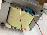
It just so happens that I started winding the brother of the OPT I made, only to run out of primary wire after 4 of the 6 layers of primary were in place. It occurred to me a little while ago that I could leave a bare spot at the top of the bobbin where I solder the new wire to finish the primary. That would make an off-centertap at the 2/3rds point. I could play with cathode feedback!ranschdow: There is no choke involved, just a transformer where the primary winding is split into two sections so that 30% goes between source and ground and the other 70% between drain and rail. Over at the Tubes forum we call it CFB or cathode feedback, it´s an old trick to make a mediocre tube behave like a very good tube, or in this case to make a lousy mosfet behave like a mediocre tube 😀
The way I see it, it´s always a good idea to make the connections between different winding sections accessible as taps, this makes the transformer more versatile for experiments. If there are two or more identical windings on a transformer I usually terminate them separately so they can be wired in series or parallel later on.
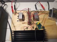
She ain´t pretty but she sure can sing... Here is the two channel prototype playing music through my horn speakers, this time with IRFP240s running at 14V 0,8A. Doesn´t sound half bad either, too bad the small cores and thin wires limits the output power to around 3W.
Attachments
I tried V+ from 45V down to 19V at about 0.8A with the IRFP240 and didn't hear much difference, same with gate bias once it was 'on' at around 5V. My non-scientific answer is that any variation in distortion due to different load lines is probably swamped by whatever mess the trafo is making 😉 , either that or my complete absence of 10,000 hours of critical listening skills is showing. I want to use old 19V laptop bricks for power if I decide to build these into monoblocks anyway.
What I would prefer to do if the second trafo is as reasonable as the first is make SIT Nemeses with my loosely matched 2SK180s. But making sure the negative gate bias comes up before V+ using laptop bricks seems complicated & also I don't know how to keep the operating point stable if there's gate current leakage with heat. 19V @ 1A isn't a great load line for these devices but again, the trafos likely predominate in this scenario.
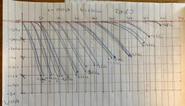
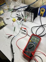
Please feel free to make fun of my kindergarden curve tracing. I'm pretty sure my Frankentracer's Y-out is referenced to ground incorrectly I just haven't gotten around to messing with it.
What I would prefer to do if the second trafo is as reasonable as the first is make SIT Nemeses with my loosely matched 2SK180s. But making sure the negative gate bias comes up before V+ using laptop bricks seems complicated & also I don't know how to keep the operating point stable if there's gate current leakage with heat. 19V @ 1A isn't a great load line for these devices but again, the trafos likely predominate in this scenario.
Please feel free to make fun of my kindergarden curve tracing. I'm pretty sure my Frankentracer's Y-out is referenced to ground incorrectly I just haven't gotten around to messing with it.
Attachments
I´m not very familiar with 2SK180 but if it is a depletion mode device perhaps autobias with a cathode resistor would work?
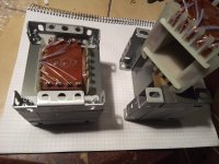
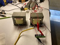
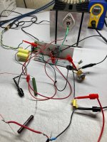
I just couldn´t stop myself from ordering two spools of 21 AWG wire and make a second attempt with larger cores. This times I wound them as 2:1 with a split for feedback at 17%. Works like a charm in the same circuit, running at 17V 0,6A until I can find a bigger heatsink.
Attachments
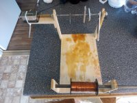
As a kid in the 60's I did my DIY projects with vacuum tubes because the tubes, transformers and other parts were often obtained free by ripping apart discarded TV's and radios. I began to tinker with solid state stuff when parts became available at Lafayette Radio Electronics, Poly Paks and other surplus dealers. Power transformers for solid state stuff were either DIY or multiple 12.6 volt filament transformers wired together. As my power hungry projects grew larger I began to dissect power transformers from old TV sets and wind new secondaries over the original primary. I never thought to try a grocery bag as the obvious choice to a teenage mind was the roll of masking tape already on my desk. I used masking tape as resist for DIY PC boards. Most of the projects I made as a kid were discarded when I left home, but a few were saved.
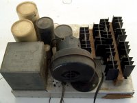
I had forgotten about a 200+ watt booster amp for guitar use that I made in high school until hurricane Wilma destroyed my shed in 2005. There amid the remains was this amp I had made in 1967. It used a 75 volt 4.5 amp surplus transformer for power and the transformer driven totem pole output circuit popular in the early germanium transistor days of the mid 60's often found with 2N2147's. I used 6 X surplus silicon parts that were sold as "2N3055's" for cheap at a local surplus shop. The trifilar driver transformer was wound on the core from a Radio Shack 6.3 volt filament transformer. As with my previous efforts I used masking tape for insulation.
What would a nearly 40 year old DIY amp that was stored outdoors in Florida do if I plugged it in? I tried it and it blew the fuse. I installed a No-Blo fuse powered it up again and one of the power supply electrolytics began to vent as the 15 amp breaker on the power strip tripped. I saved the heat sinks and discarded the rest. I took my DIY driver transformer apart to see how well it stood the test of time.
My DIY skills have improved a bit since then. This was built with a hand drill and a nibbling tool only. Aside from the rust the transformer looked OK and probably would have worked as it did in 1967. The masking tape had dried out but was still intact.
Attachments
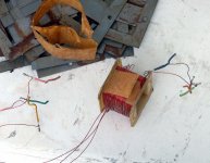
My first attempt last summer used an unpowered hand drill as the crank or shaft on which the mandril was mounted. It's hard to keep the wire feed, tension and laying going, and counting turns, while fussing with this kind of rig, but it sorta worked? The bigger problem was the nonexistent bobbin I was using, just a layer of plastic. The coil got loose as soon as it came off the mandril.My DIY skills have improved a bit since then. This was built with a hand drill and a nibbling tool only.
Attachments

Tubelab: Lovely! Years ago I visited a medieval market, the blacksmith there used a fan similar to the one in your amp to blow air into the furnace 😀
Some wishful thinking here: If I could find a depletion mode Fet that pulls ~0,8A at -0,35V g-s, then I could build an amp with only four parts that still has both gain and a relatively low output impedance 😱 The best I can do in reality is probably five parts (Fet, transformer, gate stopper, gate leak resistor and a bias resistor at the source pin) since the best Fets I can find requires about -1,5V @ 0,8A.
A cascoded LU1014 would probably be a much better choice though, WRT input capacitance.
A cascoded LU1014 would probably be a much better choice though, WRT input capacitance.
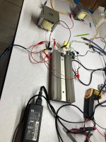
I finished the first OPT's brother today, hooked it up to an Arch Nemesis powered by a 19V laptop brick, and all was well. These trafos measure a little bit different on primary inductance from each other but that probably can't be helped, idk how important it is to hit 41Hz consistently anyway, and at least now I can attempt a stereo pair. What I want to try is a SIT Nemesis but Papa's circuit was designed for the SemiSouth SIT-1 and has zero degeneration or other resistors slowing down the current, and if I tried this circuit with a THF-51S or a 2SK180 I'm pretty sure I'd be knocked on my butt by the current draw. Looking for suggestions for drain and source degeneration so I don't shock myself out of this hobby.
Attachments
I took a quick look at the curves and it seems to me that the 2SK180 needs several volts of negative bias at the gate to keep the current down.
I got a Tokin SIT Nemesis working, first with a THF-51S and second with a 2SK180. They sound about the same, not sure they sound any better than the IRFP240 did though. I may build these up in stereo just on principle & to get them to the point where I can play them in my main system.
Deets: My negative gate bias capabilities are limited atm and so I could go no closer to zero than -3.2V, which is fine, the gates were open but I couldn't really explore other potentially interesting operating points. If I build this up I will need a proper biasing circuit from zero to at least -6V. My starting point wasn't the SIT Nemesis circuit above but the Arch Nemesis as it has all these resistors to slow things down. I used a 5R power pot on the source, a fixed 12R resistor across the secondary and either 50R or 19R across the primary. With the power pot tuned to 0R8, that circuit drew 1.4A at 45V; with the power pot at nearly a short circuit the current went up to 2.9A and the voltage sagged to 40.8V. Higher current sounded better (louder) to me, anything 1.4A and above. I didn't notice much difference in sound between 45V and 19V, again at a constant gate bias of -3.2V.
I then tried it powered by a laptop brick rated for 19V and 4.5A, with an additional 1R source resistor in line with the power pot. The THF-51S drew 0.63A, the 2SK180 drew 0.83A. No real difference in sound.
Happy Memorial Day to my fellow USAians
Attachments
- Home
- Amplifiers
- Pass Labs
- I rolled my own OPT. Then I made an Arch Nemesis with it.